
Workgroup System and Cluster Platform Express Overview and Hardware Installation Guide

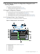
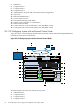
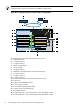
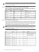

Figure B-6 c3000 Configuration with External Control Node Connection to the InfiniBand Interconnect
4
5
1
2
2
6
7
3
The following list describes the callouts shown in Figure B-6:
1. Connection from the HP 4X DDR InfiniBand Switch to the Control Node InfiniBand HCA
2. HP GbE2c switch
3. Connection from the HP GbE2c to the control node's NIC1 port
4. Connection to HP GbE2c (IMB1) from the OA external link port
5. Optional connection to an external network (for example, a campus network)
6. Onboard Administrator module
7. HP 4X DDR InfiniBand Switch — IMB3/4
Note:
Only one connection from each HP GbE2c switch is necessary in configurations with an optional
high-speed InfiniBand network.
For the administrative, console, and Gigabit Ethernet network and also the optional Infiniband
network cabling tables for CPE BladeSystem configurations, see Section B.2.
B.2 CP Workgroup System Cabling Tables
Table B-1 provides the following cabling tables:
• Cabling tables for CP Workgroup System with c3000 enclosure with single-density or
double-density server blades (see Section B.2.1)
• Cabling tables for CP Workgroup System with c3000 enclosure with the InfiniBand fabric
(see Section B.2.2)
For the port-labeling syntax for the CP Workgroup System cabling tables, see Appendix A.
B.2 CP Workgroup System Cabling Tables 69