
Workgroup System and Cluster Platform Express Overview and Hardware Installation Guide
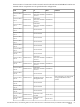
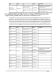

CommentLabelToLabelFrom
E1-OA1-ILO
Enclosure 1 OA1
OA/ILO
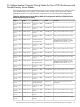
Admin-ES1-P21
ProCurve 2824
Port 21
Only Ppresent if control node is not
a server blade
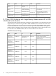
Control- NIC1
Optional External
Control Node NIC1
Admin-ES1-P22
ProCurve 2824
Port 22
Only used when an external
managed InfiniBand switch is
present
IB-SW1-NIC
InfiniBand Switch 1
Management Port
Admin-ES1-P23
ProCurve 2824
Port 23
Optional connectionControl-iLO
Optional external
control node iLO
Admin-ES1-P24
ProCurve 2824
Port 24
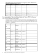
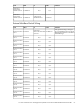
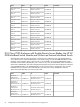
D.7 One c7000 Enclosure with Single-Density Blades and an HP 4x DDR
InfiniBand Switch Module
The following table specifies the wiring scheme for a configuration of one c7000 enclosure with
single-density server blades using the HP 4x DDR InfiniBand switch module. The table shows
the optional connections for an external control node attached to the InfiniBand fabric and for
an external InfiniBand switch that may be included to provide InfiniBand fabric management.
If either of these components are not present in the configuration or if the control node is not to
be connected to the InfiniBand fabric, the associated connections are omitted.
c7000 Enclosure Wiring
CommentLabelToLabelFrom
Only present if using a managed
24-port switch for Subnet
Management instead of a Host-Based
Subnet Manager
IB-SW1-P1
InfiniBand 24-port
Switch Port 1
E1-IMB5-P1
Enclosure 1
Interconnect
Module 5/6 Port
1
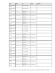
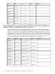
N/AN/AE1-IMB5-P2
Enclosure 1
Interconnect
Module 5/6 Port
2
N/AN/AE1-IMB5-P3
Enclosure 1
Interconnect
Module 5/6 Port
3
N/AN/AE1-IMB5-P4
Enclosure 1
Interconnect
Module 5/6 Port
4
N/AN/AE1-IMB5-P5
Enclosure 1
Interconnect
Module 5/6 Port
5
N/AN/AE1-IMB5-P6
Enclosure 1
Interconnect
Module 5/6 Port
6
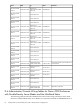
86 Cabling Tables for CPE BladeSystem, with c7000 Enclosure Configurations