
Workgroup System and Cluster Platform Express Overview and Hardware Installation Guide

CommentLabelToLabelFrom
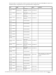
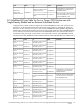
N/AN/AIB-SW1-P18
IB 24 Port Switch
Port 18
N/AN/AIB-SW1-P19
IB 24 Port Switch
Port 19
N/AN/AIB-SW1-P20
IB 24 Port Switch
Port 20
N/AN/AIB-SW1-P21
IB 24 Port Switch
Port 21
N/AN/AIB-SW1-P22
IB 24 Port Switch
Port 22
N/AN/AIB-SW1-P23
IB 24 Port Switch
Port 23
N/AN/AIB-SW1-P24
IB 24 Port Switch
Port 24
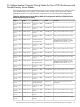
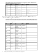
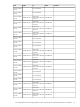
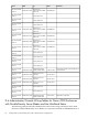
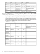
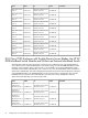
D.8 InfiniBand Wiring Table for Two c7000 Enclosures with Single-Density
Blades (Without an External InfiniBand Switch)
The following table specifies the wiring scheme for a configuration with two c7000 enclosures
wired back-to-back using the HP 4X DDR InfiniBand switch module. The connection to Enclosure
1, Interconnect Module 5/6, Port 8 depends on whether the configuration includes an external
control node connected to the InfiniBand fabric or not. If there is a control node connected to the
InfiniBand fabric, the control node’s HCA is connected to Port 8 on the InfiniBand switch installed
in Interconnect Module Bay 5/6 of the c7000 enclosure. Otherwise, that port is connected to Port
8 on the InfiniBand switch installed in Interconnect Module Bay 5/6 in Enclosure 2.
CommentsLabelToLabelFrom
E2-IMB5-P1
Enclosure 2 Interconnect
Module 5/6 Port 1E1-IMB5-P1
Enclosure 1
Interconnect
Module 5/6 Port 1
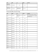
E2-IMB5-P2
Enclosure 2 Interconnect
Module 5/6 Port 2E1-IMB5-P2
Enclosure 1
Interconnect
Module 5/6 Port 2
E2-IMB5-P3
Enclosure 2 Interconnect
Module 5/6 Port 3E1-IMB5-P3
Enclosure 1
Interconnect
Module 5/6 Port 3
E2-IMB5-P4
Enclosure 2 Interconnect
Module 5/6 Port 4E1-IMB5-P4
Enclosure 1
Interconnect
Module 5/6 Port 4
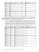
E2-IMB5-P5
Enclosure 2 Interconnect
Module 5/6 Port 5E1-IMB5-P5
Enclosure 1
Interconnect
Module 5/6 Port 5
E2-IMB5-P6
Enclosure 2 Interconnect
Module 5/6 Port 6E1-IMB5-P6
Enclosure 1
Interconnect
Module 5/6 Port 6
E2-IMB5-P7
Enclosure 2 Interconnect
Module 5/6 Port 7E1-IMB5-P7
Enclosure 1
Interconnect
Module 5/6 Port 7
88 Cabling Tables for CPE BladeSystem, with c7000 Enclosure Configurations