
Workgroup System and Cluster Platform Express Overview and Hardware Installation Guide
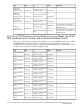
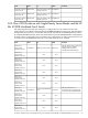
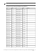

CommentLabelToLabelFrom
E1-IMB7-P5
Enclosure 1 Interconnect
Module 7/8 Port 5IB-SW1-P13
IB 24 Port Switch
Port 13
E1-IMB7-P6
Enclosure 1 Interconnect
Module 7/8 Port 6IB-SW1-P14
IB 24 Port Switch
Port 14
E1-IMB7-P7
Enclosure 1 Interconnect
Module 7/8 Port 7IB-SW1-P15
IB 24 Port Switch
Port 15
E1-IMB7-P8
Enclosure 1 Interconnect
Module 7/8 Port 8IB-SW1-P16
IB 24 Port Switch
Port 16
N/AN/AIB-SW1-P17
IB 24 Port Switch
Port 17
N/AN/AIB-SW1-P18
IB 24 Port Switch
Port 18
N/AN/AIB-SW1-P19
IB 24 Port Switch
Port 19
N/AN/AIB-SW1-P20
IB 24 Port Switch
Port 20
N/AN/AIB-SW1-P21
IB 24 Port Switch
Port 21
N/AN/AIB-SW1-P22
IB 24 Port Switch
Port 22
N/AN/AIB-SW1-P23
IB 24 Port Switch
Port 23
Only used if the control node is a
rack-mount server connected to the
InfiniBand fabric
Control-P1
Control node InfiniBand
HCA
IB-SW1-P24
IB 24 Port Switch
Port 24
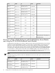
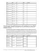
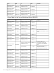
D.12 Two or Three c7000 Enclosures with Double-Density Server Blades
and Using the HP 4X DDR InfiniBand Switch Module
Configurations with either two or three c7000 enclosures and with double-density server blades
require two external InfiniBand switches to create a fully connected fabric. The wiring for two
enclosures can be derived from the three enclosure wiring tables by omitting the wiring for
Enclosure 3. The connection to Port 4 on the second external InfiniBand switch (IB-SW2) depends
on whether the configuration includes an external control node connected to the InfiniBand fabric
or not. If there is a control node connected to the InfiniBand fabric, the control node’s HCA is
connected to that port. Otherwise, Port 4 on the second InfiniBand switch is connected to Port 8
on the InfiniBand switch installed in Interconnect Module Bay 5/6 on Enclosure 1.
Note:
The following wiring table describes the InfiniBand connections with respect to the first external
InfiniBand switch.
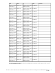
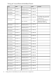
CommentLabelToLabelFrom
E1-IMB5-P1
Enclosure 1 Interconnect
Module 5/6 Port 1
IB-SW1-P1
IB Switch 1 24 Port
Switch Port 1
E1-IMB5-P2
Enclosure 1 Interconnect
Module 5/6 Port 2
IB-SW1-P2
IB Switch 1 24 Port
Switch Port 2
E1-IMB5-P3
Enclosure 1 Interconnect
Module 5/6 Port 3
IB-SW1-P3
IB Switch 1 24 Port
Switch Port 3
92 Cabling Tables for CPE BladeSystem, with c7000 Enclosure Configurations