HP Cluster Platform 24 Node Cable Management Kit Installation Guide HP Part Number: 5992-0785 Published: July 2007
© Copyright 2007 Hewlett-Packard Development Company, L.P. The information contained herein is subject to change without notice. The only warranties for HP products and services are set forth in the express warranty statements accompanying such products and services. Nothing herein should be construed as constituting an additional warranty. HP shall not be liable for technical or editorial errors or omissions contained herein. Printed in the U.S.A.
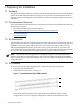
Table of Contents 1 Preparing for Installation................................................................................................6 1.1 Audience...........................................................................................................................................6 1.2 Documentation Resources.................................................................................................................6 1.3 Kit Description......................................................
List of Figures 1-1 2-1 2-2 2-3 2-4 Bracket Hardware (Top, Middle, Bottom).......................................................................................6 Bracket Orientation.........................................................................................................................8 Attaching the Bottom Retainer Bracket...........................................................................................9 Middle Bracket..............................................................
List of Tables 1-1 Fasteners..........................................................................................................................................
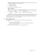
1 Preparing for Installation 1.1 Audience This guide is intended for HP service representatives and other persons trained to install hardware options in the HP 10000 Series Rack. Such persons are expected to understand the hazards of working in this environment and to take suitable precautions to minimize danger to themselves and others. 1.
management applications (consult your hardware installation documentation). The following kit features are called out in the illustration above: 1. Top retainer bracket 2. Middle spacer bracket 3. Bottom retainer bracket • The fasteners that are specified in Table 1-1. Table 1-1 Fasteners Qty. Size Format Torque Description 4 M6 cage nuts Square nut N/A Cage nut for M6 screw. 4 M6 x 16 mm Screw Screw, Phillips 30 in/lb Machine screw. For use with cage nut.
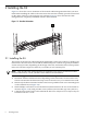
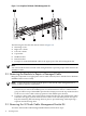
2 Installing the Kit Figure 2-1 shows the correct orientation of the 24 node cable management kit which you must install while installing the cables to the interconnect because the assembly provides strain relief for the cables. Callout 1 is the right rear rack column. Figure 2-1 shows the 24 node cable management kit completely assembled with the cables retained. Figure 2-1 Bracket Orientation 1 2.
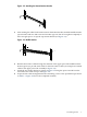
Figure 2-2 Attaching the Bottom Retainer Bracket 3 1 2 1 2 5. After running the cables for the interconnect in the bottom bracket, install the middle retainer spacer bracket with two M6 screws and two M6 cage nuts, but do not tighten completely to allow enough space to accept the top retainer bracket (see Figure 2-3). Figure 2-3 Middle Bracket 3 1 1 2 2 6. 7. 8.
Figure 2-4 Completed 24 Node Cable Management Kit 2 3 4 1 5 6 1 7 The following list describes the callouts shown in Figure 2-4. 1. Mounting screws. 2. Right rack column. 3. Left rack column. 4. Top bracket. 5. Middle bracket. 6. Bottom bracket. 7. Example of retained InfiniBand cables in the upper part of the cable management kit. Note: You must install the entire 24 node cable management kit to provide proper strain relief for the InfiniBand cables. 2.
1. 2. 3. Remove the top retainer bracket and top cables. Remove the middle spacer bracket and bottom cables. Remove the bottom retainer bracket. 2.4 InfiniBand Interconnect Removal Put the rack cabinet into a safe and stable state for component removal. You must ensure that you can reach the component easily and handle it safely. It is not necessary to remove the 24 node cable management kit to remove the InfiniBand interconnect from the rack.
*5992-0785* Printed in the US