
24 Node Cable Management Kit Installation Guide


2 Installing the Kit
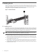
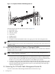
Figure 2-1 shows the correct orientation of the 24 node cable management kit which you must
install while installing the cables to the interconnect because the assembly provides strain relief
for the cables. Callout 1 is the right rear rack column. Figure 2-1 shows the 24 node cable
management kit completely assembled with the cables retained.
Figure 2-1 Bracket Orientation
1
2.1 Installing the Kit
The location of the 24 node cable management kit depends on the rack position occupied by the
interconnect. The interconnect in HP Cluster Platform Express solutions is typically installed in
a lower rack (U) location, depending on the design of the rack, and usually at the lowest position
in the rack. The kit occupies less than 1U (1.75 inches) of rack column space.
NOTE: One 24 node cable management kit is required for each 24 port system interconnect.
For more information, consult your HP Cluster Platform documentation.
Use the following procedure to install the 24 node cable management kit.
1. Determine the kit installation location depending on the interconnect location in the rack.
The kit is mounted to the bottom and top screw location for every U location the kit is used.
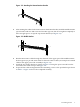
2. Mount only the bottom retainer bracket to the lowest possible bottom screw mounting hole
on the column first (see Figure 2-2).
3. With a Phillips screwdriver, secure the bottom retainer bracket to the rear rack columns as
shown in Figure 2-2 by using two M6 screws (callout 2) and two M6 cage nuts (callout 1).
4. Cable the lower interconnect as described in the HP Cluster Platform Cluster Platform Express
Installation and User's Guide.
8 Installing the Kit