
24 Node Cable Management Kit Installation Guide


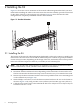
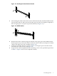
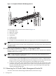

Figure 2-2 Attaching the Bottom Retainer Bracket
3
1
2
2
1
5. After running the cables for the interconnect in the bottom bracket, install the middle retainer
spacer bracket with two M6 screws and two M6 cage nuts, but do not tighten completely to
allow enough space to accept the top retainer bracket (see Figure 2-3).
Figure 2-3 Middle Bracket
3
1
2
2
1
6. Run the interconnect cables through the channels of the upper part of the middle retainer
bracket (spacer) to provide strain relief for the interconnect cables (see example of retained
cables in the upper part of the assembly in Figure 2-4).
7. Install the top retainer bracket as shown in Figure 2-4 using the space reserved from the
loosened screws used in step 5 and Figure 2-3.
8. Torque all four cable management bracket mounting screws to the specified torque shown
in Table 1-1. Figure 2-4 shows the completed assembly.
2.1 Installing the Kit 9