HP Cluster Platform AC070A Cable Management Bracket Installation Guide HP Part Number: AC070A-doc Published: October 2007 Edition: 4.
© Copyright 2007 Hewlett-Packard Development Company, L.P. The information contained herein is subject to change without notice. The only warranties for HP products and services are set forth in the express warranty statements accompanying such products and services. Nothing herein should be construed as constituting an additional warranty. HP shall not be liable for technical or editorial errors or omissions contained herein.
Table of Contents 1 Preparing for Installation................................................................................................6 1.1 Intended Audience............................................................................................................................6 1.2 Documentation Resources.................................................................................................................6 1.3 Revision History...........................................................
List of Figures 1-1 1-2 2-1 2-2 2-3 2-4 Bracket.............................................................................................................................................7 Fabric Strap......................................................................................................................................7 Aligning the Bracket with the PCI Slot of a DL380 G5, DL385 G2, or RX2660 Series Server.........9 Aligning the Bracket with the Port of DL 585 Servers (Vertical PCI Slot)...
List of Tables 1-1 Fastener Specifications....................................................................................................................
1 Preparing for Installation This chapter describes what you need to do before you begin installing an AC070A cable management bracket in an HP Rack 10000 Series cabinet. Note that such persons are expected to understand the hazards of working in this environment and to take suitable precautions to minimize danger to themselves and others.
Note: This bracket is designed to support different types of cables, from 5/16-inch (7.9-mm) minimum diameter to 5/8-inch (15.9-mm) maximum diameter. Refer to the documentation supplied with your cluster before installing the brackets and routing the cables. 1.5 Kit Contents The AC070A cable management kit contains the following components: • The bracket shown in Figure 1-1.
Table 1-1 Fastener Specifications Qty. Size • Format Torque Description 2 10-32 x .375-inch Phillips (Posidrive) 30 in/lb Machine screw, pan-head. For use with a threaded insert in the server's rail kit, or the 10-32 cage nuts. 4 M6 x 16 mm Phillips (Posidrive) 30 in/lb Machine screw, pan-head. For use with the cage nut. 4 M6 Square nut N/A Cage nut for M6 x 16-mm screw. 2 10-32 Square nut N/A Cage nut for 10-32 x .375-inch screw. Packaging and documentation.
2 Installing the Kit At the time of publication, these installation instructions apply to the specific HP servers that are identified in the installation procedures in Section 2.1. This bracket might also be adapted for other cable management uses, as specified in the installation documentation for HP Cluster Platform models. 2.
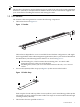
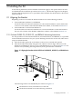
The fabric support strap. The strap is attached to the bracket slot with a single cage nut and screw. 4 The cable is routed to the cable management plate, and down to the interconnect. 5 The cable connector (shown in slot 5 in this example for the DL380 G5 and DL385 G2 servers or slot 1 for the RX2660 server), which you must secure level and square to the HCA port to prevent EMI leakage. 6 The rear right rack column. 3.
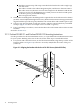
This position ensures that the center of the cable aligns with the center of the port when you secure the cable with the strap. Adjust the vertical position of the bracket until the two holes in the bracket align with two square holes in the rear rack columns. Mark the location of the square mounting holes and set the bracket aside. 2. Using a #2 Phillips screwdriver, secure the bracket to the rack column with two M6 x 16-mm screws (callout 3) and M6 cage nuts (callout 4), one on each side.
2.2 Securing Cables Using the Straps To secure a cable using the straps, follow these steps: 1. Connect the cable to the port in the PCI adapter and secure it mechanically by its clips, screws, or clamps. 2. Route the cable over the strap, loop the strap through its D-ring, and secure the strap by its hook-and-loop closure. Ensure that the cable is clamped tightly by the strap and that it cannot move. 3.
3. 4. Unstrap the cable and remove its connector from the PCI card port. When disconnecting the cable, ensure that you do not bend it more than the recommended minimum bend radius. The cable specifications are provided in the documentation for your cluster type. Unlock and slide the server all the way out of the rack, as described in the documentation for the server rack kit. 2.
*AC070A-doc* Printed in the US