
AC089A Cable Management Bracket Installation Guide (supersedes ProLiant DL380 G4 Cable Management Bracket Installation Guide)

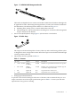
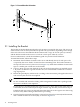


3. Insert an M6 x 16-mm fastener through the metal grommet in the strap, as shown by callout
2.
4. Use a #2 (medium) Phillips screwdriver to secure the strap loosely.
5. Perform this step only when mounting the first bracket to determine the correct horizontal
location of the strap.
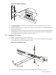
Rotate the strap (callout 3) and move it horizontally in the elongated slot to align it with the
center of the port. Using a sample cable, align the strap so that the cable's connector (plug)
is aligned correctly with the port.
Use the location of this first strap to determine the correct strap mounting position for all
subsequent bracket installations.
6. After aligning the strap, tighten the screw to its specified torque.
Repeat the installation procedure for subsequent bracket kits, using a marker pen or masking
tape to transfer the correct horizontal location of the strap to each bracket.
When all brackets are installed, consult the cabling instructions for your cluster model before
starting the cabling procedure described in Section 2.3. (See Section 1.2 for the location of the
cluster documentation.)
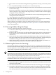
2.3 Securing Cables Using the Straps
To secure a cable using the straps, follow these steps:
1. Connect the cable to the port in the PCI adapter and secure it mechanically by its clips,
screws, or clamps.
2. Route the cable over the strap, loop the strap through its D-ring, and secure the strap by its
hook-and-loop closure. Ensure that the cable is clamped tightly by the strap and that it
cannot move.
3. Verify that the cable is square and level with the PCI port, with no strain on the connector.
This step is important to prevent possible electromagnetic interference, which can leak past
the EMI seals if the port and connector are not correctly aligned and secured.
4. When routing cables, ensure that cables remain within their bend radius specification, as
defined in the documentation for your model of HP Cluster Platform.
2.4 Removing the Server for Servicing
Use the cluster software to configure the server out of service according to the instructions in
the software documentation. Bring the component to an appropriate state for removal, and put
the rack cabinet into a safe and stable state for component removal. You must ensure that you
can reach the component easily and handle it safely.
Caution:
Consult the server and rack safety documentation before extending a server from the rack. Ensure
that you label all cables with their current port destinations before extending the server from the
rack. Two persons might be required to remove a server from the rack.
A server might have more than one Ethernet connection, and it is important that you connect
the Ethernet cables to the correct NIC ports when the server is replaced.
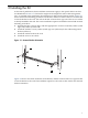
To remove the server from the rack, follow these steps:
1. Switch off the power supply from the rack's power distribution unit (PDU) and disconnect
the server's power cable.
2. Disconnect and remove each network cable until all of the networking ports are unplugged.
3. Unstrap the cable and remove its connector from the PCI card port. When disconnecting
the cable, ensure that you do not bend it more than the recommended minimum bend radius.
The cable specifications are provided in the documentation for your cluster type.
12 Installing the Kit