
Cisco SFS 7024D InfiniBand Interconnect Cable Management Brackets Installation Guide


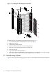
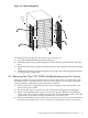

Table Of Contents
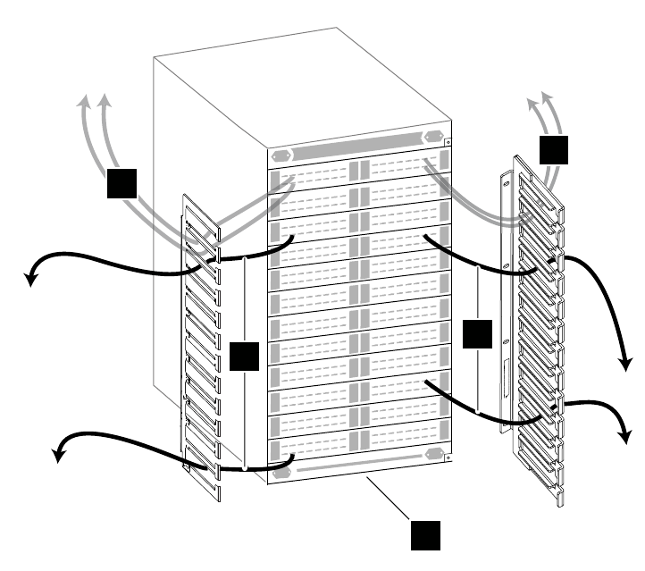
Figure 2-2 Cable Routing Options
3
4
1
4
2
3
The following list corresponds to the callouts shown in Figure 2-2.
1. Cisco SFS 7024D InfiniBand Interconnect (288 ports)
2. InfiniBand cables being routed through the left side cable management bracket (example
only)
3. InfiniBand cables being routed through the right side cable management bracket (example
only)
4. InfiniBand cables being routed through the left and right side cable management brackets
to an upper egress, if necessary.
2.2 Removing the Cisco SFS 7024D InfiniBand Interconnect for Service
Bring the component to an appropriate state for removal, and put the rack cabinet into a safe
and stable state for component removal. You must ensure that you can reach the component
easily and handle it safely. Remove the interconnect as follows:
1. Switch off the power supply from the rack's power distribution unit and disconnect the
interconnect's power cables.
2. Disconnect and remove each network cable until all networking ports are unplugged.
3. Remove the InfiniBand cables connectors from all of the ports. When disconnecting the
cables, ensure that you do not bend it more than the recommended bend radius. The cable
specifications are provided in the documentation for your cluster type.
4. Unlock and slide the interconnect all the way out of the rack, such as to reverse the installation
procedure as described in the Cisco SFS 7024D Series InfiniBand Interconnect User Manual.
2.2 Removing the Cisco SFS 7024D InfiniBand Interconnect for Service 15