
HP 16/18-Port Cable Management Kit Installation Guide (538272-doc)

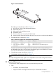
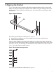
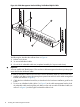

1. The U location that aligns with the top of the HP BladeSystem c7000 enclosure. Each c7000
enclosure is 10U high.
2. Mounting hook location (black square) and fastener location (circled square) for an InfiniBand
switch installed in Interconnect Module Bays (IMB) 3 and 4
3. Mounting hook location (black square) and fastener location (circled square) for an InfiniBand
switch installed in IMB 5 and 6
4. Mounting hook location (black square) and fastener location (circled square) for an InfiniBand
switch installed in IMB 7 and 8
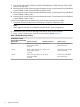
Use the following procedure to determine the actual mounting locations for brackets:
1. Determine which of the interconnect module bays contain the InfiniBand switch.
Note:
There might be more than one InfiniBand switch module in some configurations.
2. Determine the rack U location that aligns with the top of the c-Class enclosure.
3. Using a pen or masking tape, mark the mount locations defined in Table 2.
Table 2 Bracket Mounting Locations
Fastener CutoutBracket Hook CutoutRelative U Location
HP BladeSystem c7000
Enclosure Interconnect Module
Bay Numbers
Top cutout of the fourth U
down from the top
Bottom cutoutThird U down from the top
of the c-Class (c7000)
enclosure
3 and 4
Bottom cutout of the fourth U
down from the top
Center cutoutFourth U down from the top
of the c-Class (c7000)
enclosure
5 and 6
Center cutout of the fifth U
down from the top
Top cutoutFifth U down from the top of
the c-Class (c7000)
enclosure
7 and 8
8 Aligning the Bracket