HP 36-Port InfiniBand Switch Cable Management Kit Installation Guide HP Part Number: 574412-doc Published: May 2009
© Copyright 2009 Hewlett-Packard Development Company, L.P. The information contained herein is subject to change without notice. The only warranties for HP products and services are set forth in the express warranty statements accompanying such products and services. Nothing herein should be construed as constituting an additional warranty. HP shall not be liable for technical or editorial errors or omissions contained herein. InfiniBand™ is a trademark of the InfiniBand® Trade Association.
Table of Contents 1 Preparing for Installation................................................................................................5 1.1 Audience...........................................................................................................................................5 1.2 Documentation Resources.................................................................................................................5 1.3 Kit Description......................................................
1 Preparing for Installation 1.1 Audience This guide is intended for HP service representatives and other persons trained to install hardware options in the HP Rack 10000 Series. Such persons are expected to understand the hazards of working in this environment and to take suitable precautions to minimize danger to themselves and others. 1.
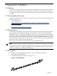
• 18 releasable cable ties shown in Figure 1-2. Figure 1-2 Releasable Cable Tie • The fasteners specified in Table 1-1. Table 1-1 Fasteners Quantity Size Format Torque Description 2 M6 cage nuts Square nut N/A Cage nut for M6 screw. 2 M6 x 16 mm Posidrive pan head screws 25-30 in/lb Machine screw. For use with M6 cage nut. To prevent screws from becoming loose because of vibration, HP recommends that you use an adjustable torque drive, set to the torque specifications given in Table 1-1.
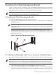
2 Installing the Cable Management Bracket Figure 2-1 shows the correct orientation of the cable management bracket that you must install before connecting the cables to the InfiniBand switch. The bracket provides strain relief for the InfiniBand ports, and maintains the correct minimum cable bend radius. Note: One cable management kit is required for each InfiniBand switch. 2.1 Installing the Cable Management Bracket To install the cable management bracket, follow these steps: 1.
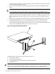
3. cable management bracket, go around the bottom cable, and then back up through the first slot in the cable management bracket. Put the releasable cable tie end through the buckle and secure the two InfiniBand cables firmly. Caution: Only hand-tighten the releasable cable tie to prevent damage to the InfiniBand cables. 4. 5. 6. Leave approximately 3/8 inch to 1/2 inch coming out of the releasable cable tie buckle and clip the excess.
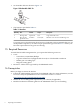
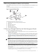
3 Removing InfiniBand Cables and Switches This chapter describes the procedure to remove a damaged InfiniBand cable or InfiniBand switch for repair. The removal procedure provided in Section 3.1 will include references to Figure 3-1. Figure 3-1 Supported InfiniBand Cables 3 4 2 6 1 5 The following list describes callouts in Figure 3-1: 1. InfiniBand cables secured with the releasable cable tie 2. Release tab 3. Releasable cable tie tail 4. Releasable cable tie 5. Releasable cable tie slot 6.
3.2 InfiniBand Switch Removal To remove an InfiniBand switch, follow these steps: 1. 2. 3. 4. Bring the InfiniBand switch to an appropriate state for service as described in the user guide for the switch. Remove all of the InfiniBand cables from the InfiniBand switch, but leave them secured in the cable management bracket. Remove the cable management bracket from the mounting rails. Leave the cables secured in the cable management bracket and carefully set the bracket aside.
*574412-doc* Printed in the US