HP BladeSystem c-Class Enclosure Cable Management Bracket Installation Guide HP Part Number: 436670-doc Published: September 2008
© Copyright 2008 Hewlett-Packard Development Company, L.P. The information contained herein is subject to change without notice. The only warranties for HP products and services are set forth in the express warranty statements accompanying such products and services. Nothing herein should be construed as constituting an additional warranty. HP shall not be liable for technical or editorial errors or omissions contained herein. InfiniBand™ is a trademark of the InfiniBand® Trade Association.
Table of Contents 1 Preparing for Installation................................................................................................7 1.1 Audience...........................................................................................................................................7 1.2 Documentation Resources.................................................................................................................7 1.3 Kit Description......................................................
List of Figures 1-1 2-1 2-2 3-1 3-2 3-3 3-4 4-1 4 Bracket Hardware...........................................................................................................................8 Bracket Orientation.......................................................................................................................11 Bracket Mounting Locations.........................................................................................................
List of Tables 1-1 2-1 Fasteners (Supplied with Cabinet Mounting Hardware)...............................................................8 Bracket Mount Locations...............................................................................................................
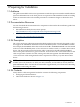
1 Preparing for Installation 1.1 Audience This guide is intended for HP service representatives and other persons trained to install hardware options in HP 10000 series racks. Such persons are expected to understand the hazards of working in this environment and to take suitable precautions to minimize danger to themselves and others. 1.
Figure 1-1 Bracket Hardware 1 2 3 5 6 4 7 The following list describes the callouts in Figure 1-1: 1. HP BladeSystem c-Class Enclosure Cable Management Bracket 2. Completed releasable cable tie assembly 3. First hole (port 1) of the inside row of holes used for the InfiniBand switch with 16 external uplink ports (489183-B21) 4. Push-button mount 5. Rail-mount hook (one on each end of the bracket) 6. Mounting hole to fasten the bracket to the rack's rear rail (one on each end of the bracket) 7.
• Tools: — Screwdriver, #2 (medium) Phillips. — Cage-nut insertion tool (shipped with the rack) or a flat-headed screwdriver. — Marker pen or masking tape. • Resources: Cables of the type used by the HP BladeSystem c-Class InfiniBand switch. 1.6 Prerequisites Before you begin to mount the bracket: • Follow the usual cable-handling precautions for InfiniBand cables, see the HP Cluster Platform InfiniBand Interconnect Installation and User's Guide.
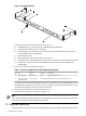
2 Aligning the Bracket Figure 2-1 shows the correct orientation of the cable management bracket which you must install before connecting the cables to the InfiniBand switch module. During the cabling procedure, the bracket provides strain relief for the InfiniBand ports, and maintains the correct minimum cable bend radius. Figure 2-1 Bracket Orientation 1 2 The following list describes the callouts shown in Figure 2-1: 1.
Figure 2-2 Bracket Mounting Locations 1 U10 U9 U8 2 U7 U6 3 The following list describes the callouts shown in Figure 2-2: 1. The U location that aligns with the top of the blades enclosure. Each enclosure is 10U high. 2. Filled squares – One of three potential cutouts (mounting holes) where you mount the bracket's hook. 3. Circled squares – One of three potential cutouts where you locate a fastener. Use the following procedure to determine the actual mounting locations for brackets: 1.
3 Installing the Cable Management Bracket The location of the c-Class enclosure cable management bracket depends on the rack position occupied by the HP BladeSystem c-Class enclosure. The InfiniBand switch might be installed in any or all of the interconnect module bays identified in Table 2-1. The kit occupies less than 1U (1.75 inches) of rack column space. 3.
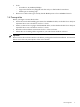
Figure 3-1 A Cable Management Bracket Holding 16 InfiniBand Uplink Cables 1 3 The following list describes the callouts shown in Figure 3-1: 1. 2. 3.
Figure 3-2 A Cable Management Bracket Holding 8 InfiniBand Uplink Cables 2 1 3 The following list describes the callouts shown in Figure 3-2: 1. 2. 3. Left rear rack column 8 secured InfiniBand cables One of the 8 releasable cable ties (completed assembly) Important: You must install the HP BladeSystem c-Class enclosure cable management bracket to provide proper strain relief for the InfiniBand cables.
Figure 3-3 InfiniBand Cable Secured with a Releasable Cable Tie 1 2 Caution: The releasable cable tie should only be hand tight. Do not use a cable tie installation tool and do not over tighten the releasable cable tie or it might damage the InfiniBand cable. 5. Leaving approximately 1/4 inch to 3/8 inch coming out of the buckle, clip the excess from the releasable cable tie.
4 Removing InfiniBand Cables and Switches This chapter describes the procedure to remove a damaged InfiniBand cable or InfiniBand switch for repair. 4.1 Removing a Damaged Cable From the c-Class Cable Management Bracket To remove a damaged cable, follow these steps: 1. Bring the HP BladeSystem c-Class enclosure to an appropriate state for service as described in the HP BladeSystem c7000 Enclosure Maintenance and Service Guide on the HP website: http://h20000.www2.hp.
3. 4. Remove the cable management bracket from the rack's rear mounting rails. Leave the cables secured in the cable management bracket and carefully set the bracket aside. Caution: Do not bend the InfiniBand cables more than the four-inch minimum bend radius. 5. 6. 18 Push the blade handle release button to release the blade handle. Open the blade handle and slide the switch all the way out of the HP BladeSystem c7000 enclosure.
*436670-doc* Printed in the US