
HP BladeSystem c-Class Enclosure Cable Management Bracket Installation Guide (436670-doc)
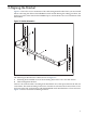
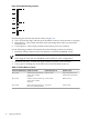
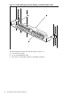


Table Of Contents
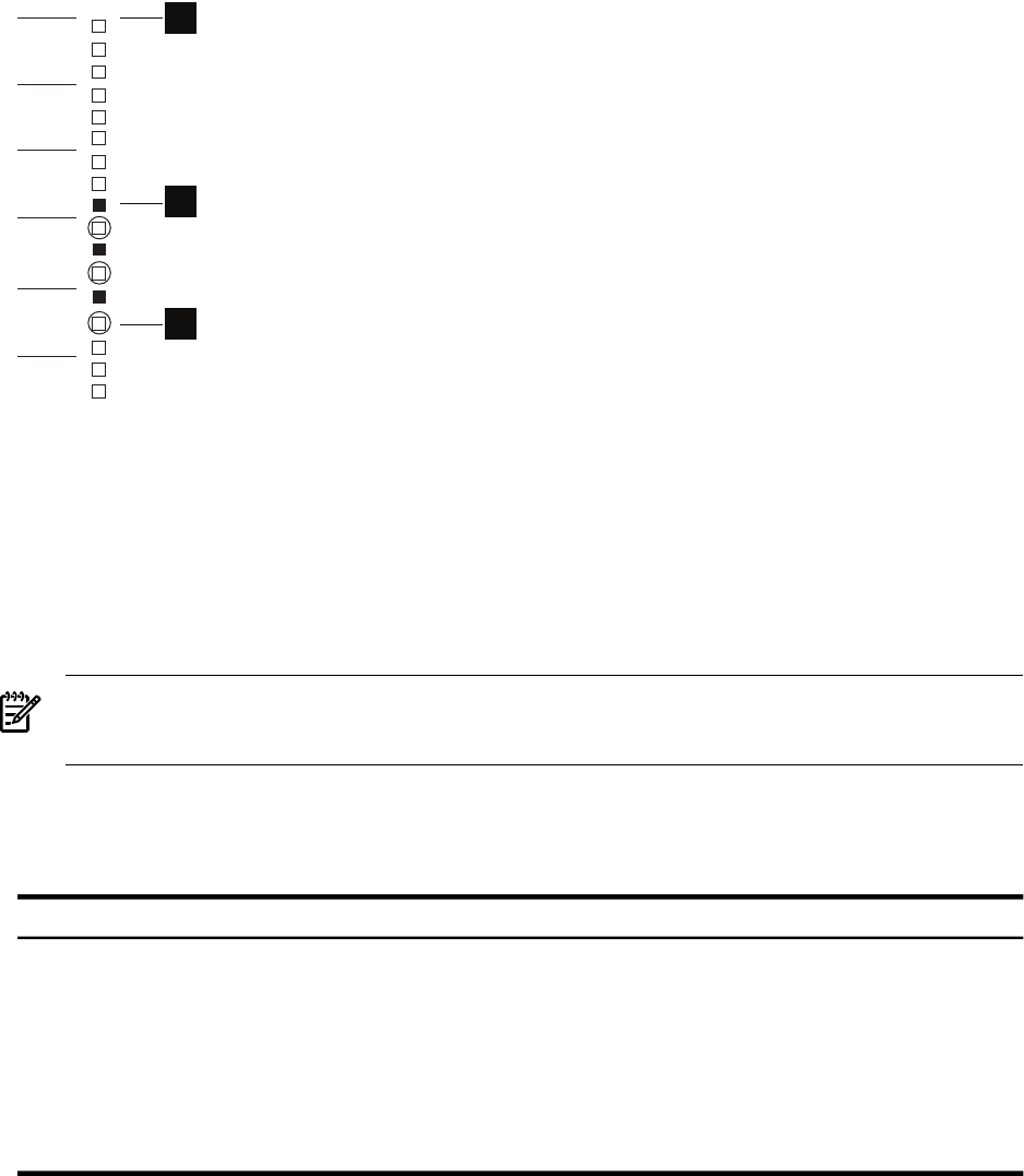
Figure 2-2 Bracket Mounting Locations
1
U10
U9
U8
U7
U6
2
3
The following list describes the callouts shown in Figure 2-2:
1. The U location that aligns with the top of the blades enclosure. Each enclosure is 10U high.
2. Filled squares – One of three potential cutouts (mounting holes) where you mount the
bracket's hook.
3. Circled squares – One of three potential cutouts where you locate a fastener.
Use the following procedure to determine the actual mounting locations for brackets:
1. Determine which of the interconnect module bays contain the InfiniBand switch.
Note:
There might be more than one InfiniBand switch module in some configurations.
2. Determine the rack U location that aligns with the top of the c-Class enclosure.
3. Using a pen or masking tape, mark the mount locations defined in Table 2-1.
Table 2-1 Bracket Mount Locations
Fastener CutoutBracket Hook Cut-outRelative U LocationInterconnect Module Bay
Top cutout of the next U
location below (fourth U)
Bottom cutoutThird U down from the top
of the c-Class (c7000)
enclosure
Bay 3 and 4
Bottom cutoutCenter cutoutFourth U down from the top
of the c-Class (c7000)
enclosure
Bay 5 and 6
Center cutoutTop cutoutFifth U down from the top of
the c-Class (c7000) enclosure
Bay 7 and 8
12 Aligning the Bracket