
HP Cluster Platform 435761-B21 Cable Management Bracket Installation Guide


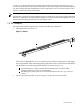
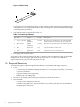
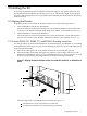

Figure 1-2 Fabric Strap
1
3
2
Each strap has a hook-and-loop fabric closure (callout 1) and a metal D-ring (callout 2) that
is designed to secure a single interconnect cable. The straps are secured to the bracket through
a metal grommet (callout 3).
• The fasteners that are specified in Table 1-2.
Table 1-2 Fastener Specifications
DescriptionTorqueFormatSizeQty.
Machine screw, pan-head. For use with a threaded
insert in the server's rail kit, or the 10-32 cage nuts.
30 in/lbPhillips
(Posidrive)
10-32 x .375-inch2
Machine screw, pan-head. For use with the cage nut.30 in/lbPhillips
(Posidrive)
M6 x 16 mm4
Cage nut for M6 x 16-mm screw.N/ASquare nutM64
Cage nut for 10-32 x .375-inch screw.N/ASquare nut10-322
• Packaging and documentation.
To prevent screws from becoming loose due to vibration, HP recommends using an adjustable
torque driver set to the torque specifications given in Table 1-2. Contact your HP sales
representative if any parts are missing from your kit.
1.6 Required Resources
To install the generic cable management bracket kit, you need the following resources:
• Tools:
— A 6-inch long #2 (medium) Phillips (Posidrive or cross-point) screwdriver, or #2 bit for
a power screwdriver.
— Cage-nut insertion tool (optional).
— Marker pen or masking tape.
• Resources: A sample cable of the type used by the system interconnect.
• Environment:
— A work surface adjacent to the rack.
— A stable work platform or step stool that lets you safely reach the servers installed in
the upper part of the rack.
8 Preparing for Installation