HP Cluster Platform 435762-B21 Cable Management Bracket Installation Guide HP Part Number: 435762-B21-doc Published: October 2008 Edition: Third Edition
© Copyright 2008 Hewlett-Packard Development Company, L.P. The information contained herein is subject to change without notice. The only warranties for HP products and services are set forth in the express warranty statements accompanying such products and services. Nothing herein should be construed as constituting an additional warranty. HP shall not be liable for technical or editorial errors or omissions contained herein.
Table of Contents 1 Preparing for Installation................................................................................................6 1.1 Audience...........................................................................................................................................6 1.2 Documentation Resources.................................................................................................................6 1.3 Revision History.....................................................
List of Figures 1-1 1-2 2-1 2-2 2-3 2-4 4 435762-B21 Cable Management Bracket.........................................................................................7 Fabric Strap......................................................................................................................................7 Outer Bracket Orientation...............................................................................................................9 Inward Bracket Orientation..............................
List of Tables 1-1 1-2 Revision History..............................................................................................................................6 Fasteners..........................................................................................................................................
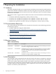
1 Preparing for Installation 1.1 Audience This guide is intended for HP service representatives and other persons trained to install hardware options in the HP Rack 10000 Series cabinet. Note that such persons are expected to understand the hazards of working in this environment and to take suitable precautions to minimize danger to themselves and others.
Note: This bracket is designed to support different types of cables, from a 5/16-inch (7.9-mm) minimum diameter to a 5/8-inch (15.9-mm) maximum diameter. Consult the documentation supplied with your cluster before installing the brackets and routing the cables. 1.5 Kit Contents The 435762-B21 cable management bracket kit contains the following components: • The bracket shown in Figure 1-1.
Table 1-2 Fasteners (continued) • 1 M6 Square nut N/A Cage nut for M6 x 16-mm screw. 2 10-32 Square nut N/A Cage nut for 10-32 x .375-inch screw. Packaging and documentation. To prevent screws from becoming loose because of vibration, HP recommends that you use a torque screwdriver set to the torque specifications given in Table 1-2. Contact your HP sales representative if any parts are missing. 1.
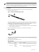
2 Installing the Kit At the time of publication, these installation instructions apply to the specific HP servers that are identified in Section 1.1. This bracket might also be adapted for other cable management uses, as specified in the installation documentation for HP Cluster Platform models. Figure 2-1 shows the two mounting positions for the bracket, and the location of the two case nuts if the server's rail kit is already installed in the rack.
Figure 2-2 Inward Bracket Orientation 4 U1 U2 4 3 2 5 1 3 2 2.1 Installing the Bracket The location of the bracket depends on the rack position occupied by the server. The servers in an HP Cluster Platform rack are always installed at specific rack (U) locations, depending on the design of the rack. The servers described in this document each occupy 2U of rack space (3.5 inches) and the bracket installs in the lower U of each 2U of rack space taken by a server.
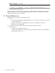
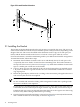
Figure 2-3 Aligning the Bracket 5. 6. 7. Using a #2 Phillips screwdriver, secure the bracket to the cage nuts by using two 10-32 x .375-inch fasteners. Before installing the server, verify that it contains a PCI interconnect card installed in slot 3 (the lowest PCI slot). Follow the rail kit instructions to attach the rails to the server and insert it in the track.
5. Perform this step only when mounting the first bracket to determine the correct horizontal location of the strap. Rotate the strap (callout 3) and move it horizontally in the elongated slot to align it with the center of the port. Using a sample cable, align the strap so that the cable's connector (plug) is aligned correctly with the port. Use the location of this first strap to determine the correct strap mounting position for all subsequent bracket installations. 6.
4. 5. Temporarily loop the interconnect cable over the bracket and secure it loosely with the strap to ensure that it is undamaged while you work on the server. Do not let the cable hang by its own weight or exceed its minimum bend radius. After verifying that all cables are disconnected, unlock and slide the server all the way out of the rack, as described in the documentation for the server rack kit. Never extend more than one server at a time without removing the server from the rack completely.
*435762-B21-doc* Printed in the US