
HP Cluster Platform 435762-B21 Cable Management Bracket Installation Guide


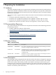
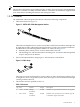

Table Of Contents
Figure 2-2 Inward Bracket Orientation
2
U1
U2
4
4
5
3
3
1
2
2.1 Installing the Bracket
The location of the bracket depends on the rack position occupied by the server. The servers in
an HP Cluster Platform rack are always installed at specific rack (U) locations, depending on the
design of the rack. The servers described in this document each occupy 2U of rack space (3.5
inches) and the bracket installs in the lower U of each 2U of rack space taken by a server.
For more information, consult the installation guide for your HP Cluster Platform configuration.
To install the bracket, follow these steps:
1. Determine the installation location for the server and identify the 2U of rack space to be
occupied by the server. Each U location has three mounting holes. The bracket mounts at
the top hole of the lower U (shown as U2 in Figure 2-2). Mark the installation location with
tape or a marker pen on both rear rack columns.
2. Clip two 10-32 cage nuts into the back of the rack at the locations that you marked in step
1. If you do not have the cage nut insertion tool, use a flat-bladed screwdriver to ease the
cage clip in place.
3. Mount the quick-deploy rail kit track, according to the instructions packaged with server's
rack accessory kit. No tools are required.
Note:
Do not assemble and mount the folding cable management bracket that is packaged with
the server's rail kit. It is not required.
Each track has a mounting flange that contains accessory holes. Ensure that when the track
is mounted, the lowest accessory hole aligns with the cage nut that you inserted in step 2.
If the hole and cage nut are not aligned, then either the track or the cage nut is in the wrong
location. Verify the mounting location before proceeding.
4. Place the bracket against the rail flanges so that it faces inward (or outward) and downward,
and is within the lower U location (U2), as shown in Figure 2-3.
10 Installing the Kit