HP ProCurve 2610 Series Rail Kit Installation Guide HP Part Number: 508783-doc Published: November 2008
© Copyright 2008 Hewlett-Packard Development Company, L.P. The information contained herein is subject to change without notice. The only warranties for HP products and services are set forth in the express warranty statements accompanying such products and services. Nothing herein should be construed as constituting an additional warranty. HP shall not be liable for technical or editorial errors or omissions contained herein. Printed in the U.S.A.
Table of Contents 1 Preparing for Installation................................................................................................7 1.1 Audience...........................................................................................................................................7 1.2 Documentation Resources.................................................................................................................7 1.3 Overview of the Installation Procedure...............................
List of Figures 1-1 1-2 1-3 2-1 2-2 2-3 2-4 2-5 4 HP ProCurve 2610 Series Rail Kit Hardware..................................................................................8 Support Bracket...............................................................................................................................9 Bracket Orientation.......................................................................................................................10 Attach the Support Brackets.......................
List of Tables 1-1 Fasteners..........................................................................................................................................
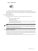
1 Preparing for Installation 1.1 Audience This guide is intended for HP service representatives and other persons trained to install hardware options in HP 10000 Series racks. Such persons are expected to understand the hazards of working in this environment and to take suitable precautions to minimize danger to themselves and others. 1.
• The fasteners specified in Table 1-1. Table 1-1 Fasteners • • Quantity Size Format Torque Description 8 M4 x 0.7 x 8 mm screw Phillips (Posidrive) 15 in-lb Rack-mount bracket mounting screw (flat-head). 8 M6 cage nut N/A N/A Cage nut for M6 x 16 mm machine screw. A round nut that clips into the rack column. 10 M6 x 16 mm Pan Head XRCS screw 30 in-lb Rack-mount bracket mounting screw. Packaging and documentation. The bracket hardware shown in Figure 1-1 and Figure 1-2.
Figure 1-2 Support Bracket • Contact your HP representative if any parts of the kit are missing or damaged. The HP ProCurve 2610 Series rail kit is used for HP ProCurve 2610 Series switches; however, it might be adapted for use in other rack-mount applications (see the installation documentation for your hardware). 1.
Figure 1-3 Bracket Orientation 4 2 6 4 3 1 5 Figure 1-3 shows the following components and their orientation to the HP ProCurve 2610 Series switch. 1. Left mounting bracket. 2. Right mounting bracket. 3. The ProCurve 2610 series switch. 4. Support bracket mounting position. See Figure 2-1 for more information on where and how to mount the support bracket. 5. M6 screws. 6. M4 screws. 1.8 Installation Preparations Prepare for the installation as follows: 1.
2 Installing the HP ProCurve 2610 Series Rack Mount Brackets The installation location for your HP ProCurve 2610 Series switch depends on the configuration rules for your system. See Section 1.2 for more information on ProCurve products and other documentation resources. Your configuration includes other servers, switches, and cables. Each component occupies a specific rack location so that the intercomponent cabling is correct. To install the HP ProCurve 2610 Series rail kit, follow these steps: 1.
Caution: Use only the specified screws. Screws that are too long might penetrate the switch chassis and cause damage to internal components. Figure 2-2 Attach the Mounting Brackets 3 1 2 5. The mounting brackets are not symmetrical. One mounting bracket is for the left side and one is for the right side.
Figure 2-4 HP ProCurve 2610 Series Switch Attached to Front of the Rack 7. Tighten all of the screws to the recommended torque (see Table 1-1 for the recommendations). Note: HP recommends that you use an adjustable torque drive set to the torque specifications provided in Table 1-1. The assembly and installation is completed as shown in Figure 2-5.
3 Cabling and Power Follow the installation instructions for your cluster configuration bundle that was shipped with this kit. See Section 1.2 for information on where you can obtain product documentation resources. It is important that you connect the servers to the correct network cables and interconnect cables, and that you apply power in the correct sequence.
4 Removing an HP ProCurve 2610 Series Switch for Servicing Bring the cluster to an appropriate state and put the rack into a safe and stable state for component removal. You must ensure that you can easily reach the switch and handle it safely. For more information on how to do this, see the ProCurve Switch 2610 Series Installation and Getting Started Guide. To remove an HP ProCurve 2610 Series switch from a rack, reverse the steps shown in this document's installation procedure.
*508783-doc* Printed in the US