
HP ProCurve 2610 Series Rail Kit Installation Guide (508783-doc)


2 Installing the HP ProCurve 2610 Series Rack Mount
Brackets
The installation location for your HP ProCurve 2610 Series switch depends on the configuration
rules for your system. See Section 1.2 for more information on ProCurve products and other
documentation resources. Your configuration includes other servers, switches, and cables. Each
component occupies a specific rack location so that the intercomponent cabling is correct.
To install the HP ProCurve 2610 Series rail kit, follow these steps:
1. The HP ProCurve 2610 Series switch and assembled rail kit occupies 1U (1.75 inches) of
space in the rack. Each 1U rack location is numbered 01-42 from the bottom to the top of the
rack columns. There are three mounting holes for each 1U of space in the outer rail of the
rack (see callout 1 in Figure 2-1). For ease of reference, mark the desired column positions
with tape or a marker pen.
2. Place two of the M6 cage nuts in the top and bottom holes of the desired U location on both
the right and left front secondary mounting rails (see callout 4 in Figure 2-1).
3. Locate the same U location on the right and left secondary mounting rails of the rack and
attach one support bracket (callout 3 in Figure 2-1) using two M6 screws (callout 2 in
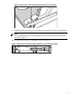
Figure 2-1) on each side. Figure 2-1 shows the outer rail of the rack (callout 1) and the support
bracket (callout 3) attached to the secondary mounting rail. Note that the support bracket
is extended toward the front of the rack as shown in Figure 2-1.
Figure 2-1 Attach the Support Brackets
4
29
3
2
1
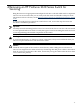
4. Mount the left and right mounting brackets to the HP ProCurve 2610 Series switch using
the M4 x 0.7 x 8 mm screws. There are four screws for each mounting bracket (see callout 6
in Figure 1-3).
11