HP Cluster Platform HP ProLiant DL16x Server Cable Management Bracket Installation Guide HP Part Number: 498442-doc Published: June 2008
© Copyright 2008 Hewlett-Packard Development Company, L.P. The information contained herein is subject to change without notice. The only warranties for HP products and services are set forth in the express warranty statements accompanying such products and services. Nothing herein should be construed as constituting an additional warranty. HP shall not be liable for technical or editorial errors or omissions contained herein. Printed in the U.S.A.
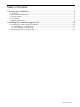
Table of Contents 1 Preparing for Installation................................................................................................6 1.1 Audience...........................................................................................................................................6 1.2 Documentation Resources.................................................................................................................6 1.3 Kit Description......................................................
List of Figures 1-1 1-2 1-3 2-1 2-2 2-3 2-4 2-5 Cable Management Bracket............................................................................................................7 3.5 Inch Fabric Strap........................................................................................................................7 5.0 Inch Fabric Strap........................................................................................................................8 Cable Management Bracket Orientation.......
List of Tables 1-1 Fasteners..........................................................................................................................................
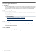
1 Preparing for Installation 1.1 Audience This guide is intended for HP service representatives and other persons trained to install hardware options in HP 10000 Series Racks. Such persons are expected to understand the hazards of working in this environment and to take suitable precautions to minimize danger to themselves and others. 1.
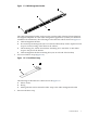
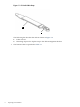
Figure 1-1 Cable Management Bracket 4 1 2 3 The cable management bracket can be used in several models of the HP Cluster Platform and might be adaptable for other cable management applications (consult your hardware installation documentation). The following list describes the callouts shown in Figure 1-1: 1. Cable management bracket 2. Five inch strap mounting hole (one on each end of the bracket) used to clip the five inch strap for vertical routing of the cables in the cabinet. 3.
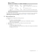
Figure 1-3 5.0 Inch Fabric Strap 1 2 The following list describes the callouts shown in Figure 1-3: 1. Fabric closure 2. Mounting clip used to clip the strap to the cable management bracket • 8 The fasteners that are specified in Table 1-1.
Table 1-1 Fasteners • Qty. Size Format Torque Description 2 M6 Cage Nuts Square Nut N/A Cage nut for M6 x 16 mm screw. 2 M6 x 16 mm Screws Screw, Phillips 30 in/lb Machine screw, Phillips drive. For use with the cage nut. 2 10–32 Clip Nut Nut, Clip N/A For use with the 10–32 screws. 2 10–32 x 0.625 Screws Screw, Phillips 30 in/lb Machine screw, pan-head. For use with the clip nut. Packaging and documentation.
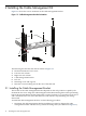
2 Installing the Cable Management Kit Figure 2-1 shows the correct orientation of the cable management bracket. Figure 2-1 Cable Management Bracket Orientation 3 2 1 5 4 6 7 The following list describes the callouts shown in Figure 2-1: 1. HP ProLiant DL16x G5 1U server 2. Left rear rack column 3. Right rear rack column 4. Cable management bracket 5. PCI slot 6. Mounting screw and cage nut 7. Direction of view looking in from the rear of the 10K rack 2.
2. 3. Ensure that the cable management bracket's strap mounting face is lined up with the PCI slot as shown in Figure 2-1. The strap mounting face radius' should face downward so as not to damage the InfiniBand cables. Fasten the cable management bracket to the rack's rear rails by removing both of the top rail kit mounting screws. Fasten the cable management bracket to the rear rail with the two 10–32 screws provided in the cable management bracket installation kit.
2.1.2 Installing the 5.0 Inch Strap To install the five inch strap, use the following procedure: 1. Verify that the cables are square and level with the ports, with no strain on the connector. This step is important to prevent possible electromagnetic interference, which can leak past the EMI seals if the port and connector are not correctly aligned and secured. 2. Clip the five inch strap to the mounting hole (see callout 1 in Figure 2-3) on the cable management bracket. Figure 2-3 Attaching the 5.
Figure 2-5 Cable Routing Example 2 2.2 Removing the Server for Servicing Bring the component to an appropriate state for removal, and put the rack cabinet into a safe and stable state for component removal. You must ensure that you can reach the component easily and handle it safely. Remove the unit as follows: 1. Switch off the power supply from the rack's power distribution unit and disconnect the power cable. 2. Disconnect the InfiniBand connector from the PCI port and unstrap the cables (if necessary).
*498442-doc* Printed in the US