HP Cluster Platform HP Integrity rx4640 Cable Bracket Installation Guide Part Number: AA-RWL0A-TE October 2004 This document describes how to install the HP Integrity rx4640 server cable bracket. The kit consists of a rail-mounted bracket and three cable retainer straps. The bracket and straps are designed to support the weight of the interconnect cable and to hold the cable’s connector in line with the PCI card socket.
© Copyright 2004 Hewlett-Packard Development Company, L.P. The information contained herein is subject to change without notice. The only warranties for HP products and services are set forth in the express warranty statements accompanying such products and services. Nothing herein should be construed as constituting an additional warranty. HP shall not be liable for technical or editorial errors or omissions contained herein. Printed in the U.S.A.
1 HP Integrity rx4640 Cable Bracket Installation Guide 1.1 Audience HP service representatives and other persons trained to install hardware mounting options and system components in the HP Model 10642 rack. Such persons are expected to understand the hazards of working in this environment and to take suitable precautions to minimize danger to themselves and others. 1.
To prevent screws from becoming loose due to vibration, HP recommends that you use an adjustable torque driver set to the torque specifications given in Table 1-1. Contact your HP sales representative if any parts are missing. 1.4 Bracket Overview and Features A bracket is required for every server containing a PCI card that is connected to the cluster’s interconnect. Depending on the type of interconnect, the cable diameter might vary.
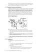
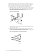
For information about the rail kit, see the Installation Guide for Midweight Slide Kit that is shipped with each HP Integrity rx4640 server. 1.6 Installing the Bracket Install the bracket as follows: 1. Mount the bracket on the end of the rail, as shown in Figure 1-2: Figure 1-2: Mounting the Bracket on the Rail RX4640 Left Rail Cable Management Bracket Left Rear Rack Column HPTC-0059 2. a. Position the bracket on the end of the rail, as shown in Figure 1-2. b.
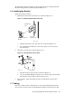
cabling instructions are designed to ensure that the correct number of cables are grouped and bound together. The weight of each cable bundle must be supported by the various cable management straps located throughout the rack. When connecting the cable to the server’s PCI card, use the following procedure: 1. Working from the top of the rack downward, connect each cable to the specified port on the PCI card. Route the cable over the bracket and the 3.5-inch strap.
1.8 Removing the Server for Servicing Bring the system to an appropriate service state, and put the rack cabinet into a safe and stable state for component removal. You must ensure that can you can easily reach the component and handle it safely. 1. Switch off the power supply from the rack’s power distribution unit and disconnect the server’s power cable. 2. Disconnect and remove each network cable until all networking ports are unplugged. 3. Unstrap the cable at the 3.