HP Linux Clusters QsNetII Cable Management Kit Installation Guide Part Number: AA-RVWCA-TE March 2004 Revision/Update Information: This is a new manual. This document describes how to install the QsNetII Cable Management Kit into an HP Model 10642 rack.
© Copyright 2004 Hewlett-Packard Development Company, L.P. The information contained herein is subject to change without notice. The only warranties for HP products and services are set forth in the express warranty statements accompanying such products and services. Nothing herein should be construed as constituting an additional warranty. HP shall not be liable for technical or editorial errors or omissions contained herein. Quadrics® is a registered trademark and QsNetII™ is a trademark of Quadrics Ltd.
QsNet Cable Management Kit Installation Guide II You use this kit when installing a QsNetII™ interconnect into an HP Linux® Cluster. This kit offers the following features: • Provides strain relief for connectors, maintaining the alignment of plugs and ports with the specified 10 degree limit of deviation from horizontal. • Maintains the bend radius of the cables within the specified tolerances. • Facilitates organization and routing of the cables.
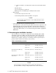
• Eight cable management bars, identified by callout 1 in Figure 1. Each bar provides 16 cable hooks. There is a spring-loaded retainer pin at the top of each bar, identified by callout 2 in Figure 1. • Two rear bar brackets, which stand off the rear rack columns and are identified as follows: • - An upper rear bracket, which provides four retainer holes for the spring-loaded pins at the top of each bar. This bracket is identified by callout 3 in Figure 1.
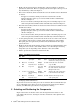
Figure 1: Rack Orientation Cage Nut M6 5 3 2 1 4 6 M6 x 16mm Screw Rear of Rack Front of Rack zk-2077 6 Preparing for Installation Prepare for installation as follows: • Ensure that the cluster is shut down and powered off so that you can perform the installation. • Remove the rack front and rear doors and side panels for ease of installation. Verify that the rack is secure and stable enough to work on, and always install the lowest components first.
3 • Offset screwdriver (or ratchet driver) with a 0.25-inch wide flat-blade tip. - T25 Torx driver. - Cage nut insertion tool (optional). - Marker, pencil, or masking tape to identify mount locations. Environment: - A work surface adjacent to the rack. - A small work platform, stable stepladder, or step stool. _____________________ Caution ____________________ Always install components into a rack working from the bottom of the rack upwards.
and might prevent the removal of field-replaceable components, such as the interconnect’s cooling fan tray. 9 Installing the Kit Install the kit as follows: 1. If you are installing this cable management kit into an Interconnect Building Block (IBB) that contains two interconnects, you must first install the cable guide plates as described in step 1. If you are installing the kit into an IBB that contains one interconnect in the lower rack location only, you do not need to install the cable guide plate.
_____________________ Note _____________________ Hand-tighten the thread-forming screw to avoid overtightening it. Overtightening can easily strip out the formed thread. d. Repeat steps a through c for the right-hand plate, if required. (Typically, you need to install the right-hand plate only if more than half the interconnect’s ports are in use.) 2. Using the information in Table 2, determine the rack location and mark the fastener mounting positions on the rack columns.
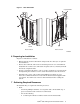
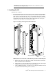
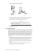
Figure 4: Securing the Rear Bottom Bracket M6 Cage Nut (4X) M6 x 16mm Screw (4X) Rear of Rack zk-2081 5. Prepare the eight cable support bars for installation by retracting the spring-loaded retainer pin at the top of each bar. Pull the pin down and rotate it until the pin locks in the retracted position as shown in Figure 5. Figure 5: Locking the Retainer Pin X Y 1 Pin in Closed Position Pin in Open Position zk-2082 6.
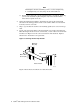
Figure 6: Inserting a Bar and its Pivot Pin X Y zk-2083 7. Swing the bar upward and align the locking pin with its corresponding hole in the top bracket. Release the locking pin, securing the bar in place. 8. Using a flat-blade screwdriver, hand-tighten the pivot pin. _______________________ Note _______________________ Because of the position of adjacent set of flanges, it may be difficult to insert the screwdriver blade in the pin’s slot. An offset screwdriver is recommended. 9.
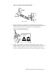
Figure 7: Cabling the Interconnect 2 1 3 zk-2084 5. Slide the cable forward until its connector aligns with the port (callout 3 in Figure 7), and secure the cable by pushing only on the metal connector body (callout 2 in Figure 7). Ensure that you keep the connector level and square with the port as you insert it. 6. Repeat steps 2 through 5 for all remaining cables. If you are installing an interconnect into the upper part of the rack, proceed to step 7.
c. When securing cables with the strap, loop the end of the strap through the metal D ring and secure it with the hook-and-loop closure (callout 3). d. Repeat steps a through c for the remaining straps. 11 Servicing the Interconnect To service the interconnect, use the following procedures. Replacing a Cable Use the following procedure to replace a malfunctioning cable: 1. Consult the documentation for your interconnect to determine the link (cable) removal prerequisites.
12 Removing the Cable Management Kit Remove the rear cable management brackets and bars only if you are removing an entire interconnect chassis. You remove the interconnect chassis by sliding it out of the rear of the rack. If the cables are not labeled for their respective ports, you might want to label them prior to disconnecting any cables.