
Linux Clusters QsNetII Cable Management Kit Installation Guide


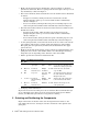
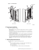
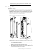
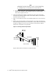
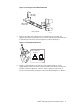
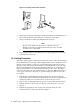

Figure 6: Inserting a Bar and its Pivot Pin
zk-2083
Y
X
7. Swing the bar upward and align the locking pin with its corresponding hole in
the top bracket. Release the locking pin, securing the bar in place.
8. Using a flat-blade screwdriver, hand-tighten the pivot pin.
_______________________ Note _______________________
Because of the position of adjacent set of flanges, it may be
difficult to insert the screwdriver blade in the pin’s slot. An offset
screwdriver is recommended.
9. Repeat steps 8 and 9 for the remaining seven cable support bars on both the
front and back of the rack.
10 Cabling Procedure
Follow the cabling sequence instructions for the interconnect cables as described in
the documentation for your cluster. The cabling instructions are designed to ensure
that the correct number of cables are grouped and bound together, then routed
along the rack’s cable management system. It is important that you use the cable
management guidelines for the specific installation that you are configuring and
that you maintain the correct maximum bend radius for the cables. Bending a
cable beyond its limit can cause internal damage to the cable, EMI interference, or
cause a poor connection at the ports. A general cabling procedure for each cable
is as follows:
1. Following the cabling diagrams and procedures for your cluster, plan the
route for the cables and determine the direction from which you will begin the
routing procedure (server-to-interconnect or interconnect-to-server).
2. Route a cable, feeding it through the open raceway beneath the interconnect.
3. Working from the bottom up at each 16-port card, remove the cover from
the port.
4. Identify the appropriate cable for the port and hook it into the cable
management bar as shown by callout 1 in Figure 7.
8 QsNet
II
Cab le Management Kit Installation Guide