
Linux Clusters QsNetII Cable Management Kit Installation Guide

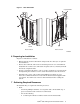
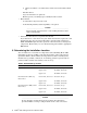
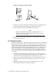

• Eight cable management bars, identified by callout 1 in Figure 1. Each bar
provides 16 cable hooks. There is a spring-loaded retainer pin at the top of each
bar, identified by callout 2 in Figure 1.
• Two rear bar brackets, which stand off the rear rack columns and are identified
as follows:
- An upper rear bracket, which provides four retainer holes for the
spring-loaded pins at the top of each bar. This bracket is identified by
callout 3 in Figure 1.
- A lower rear bracket, which provides four pairs of mounting lugs for each
cable management bar. This bracket is identified by callout 4 in Figure 1.
• Two front bar brackets, which are inset between the front rack columns and are
identified as follows:
- An upper front bracket, which provides four retainer holes for the
spring-loaded pins at the top of each bar. This bracket is identified by
callout 5 in Figure 1.
- A lower front bracket, which provides four pairs of mounting lugs for each
cable management bar. This bracket is identified by callout 6 in Figure 1.
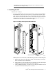
• A cable guide plate that you attach to the frame at the rear of the rack (not the
rack columns) and provides a routing guide and support for cable bundles.
This guide plate is required only for interconnects installed into the upper
part of the rack.
• Eighteen straps with hook-and-loop closures, which are supplied with the cable
guide plate to secure the cable bundles. There are 9 short straps and 9 long
straps that you use depending on the diameter of the cable bundle.
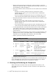
• Table 1 specifies the fasteners included in the kit.
Table 1: Installation Kit Fasteners
Qty. Size
Type Tool Torque Description
8 10–32
Shoulder screw
(pivot pin)
Flat-
blade
Hand-
tight
Secures the cable management
bar to the lower bracket and
enables it to swing up or down.
16
M6 x 16
mm
Pan-head
machine screw
Phillips
(Posidrive)
30 in/lb Pan-head screw used with
cage nut M6.
16
M6 Cage nut Cage nut
insertion
tool
N/A An enclosed nut that clips onto
the rack columns. Used with
M6 pan-head screw.
2
10-32 x .5” Pan-head
thread-forming
screw
Phillips
(Posidrive)
N/A Attaches the cable guide plate
to the horizontal rack frame.
9
M5 x 10
mm
Pan-head
machine screw
T25 Torx 30 in/lb Attaches the straps to the
cable guide plate.
• Packaging and documentation.
To prevent screws from becoming loose due to vibration, HP recommends that you
use an adjustable torque driver set to the torque specifications given in Table 1.
Contact your HP sales representative if any parts are missing.
5 Orienting and Positioning the Components
Figure 1 shows the orientation of the cable management bars relative to the
rack and the interconnect. See Figure 2 for the orientation of the optional cable
guide plate.
2 QsNet
II
Cable Management Kit Installation Guide