HP Cluster Platform ProCurve 1U Rack Mount Bracket Installation Guide HP Part Number: 5991-7451 Published: November 2006
© Copyright 2006 Hewlett-Packard Development Company, L.P. The information contained herein is subject to change without notice. The only warranties for HP products and services are set forth in the express warranty statements accompanying such products and services. Nothing herein should be construed as constituting an additional warranty. HP shall not be liable for technical or editorial errors or omissions contained herein. Printed in the U.S.A.
1 Preparing for Installation 1.1 Audience This guide is intended for HP service representatives and other persons trained to install hardware options in HP 10000 Series racks. Such persons are expected to understand the hazards of working in this environment and to take suitable precautions to minimize danger to themselves and others. 1.
• The fasteners specified in Table 1-1. Table 1-1 Fasteners • • Quantity Size Format Torque Description 8 M4 x 8 mm Phillips (Posidrive) 15 in-lb Rack mount bracket mounting screw (flat-head). 8 10–32 x 0.625 Pan Head XRCS 30 in-lb Slide bracket mounting screw location A (rear column) and location B (front column). 4 10–32 Cage Nut Square Nut N/A Cage nut for 10–32 machine screw. A square nut that clips into the rack column.
— — — • Cage-nut insertion tool (shipped with the rack). Marker pen or masking tape. Short stepladder or platform that enables you to install brackets in the upper part of the rack. Resources: Cables of the type used by the ProCurve switch being installed. Note: Although the ProCurve switch is not a heavy component, you might need to install it in an elevated location in the rack. In such cases, HP recommends that two people are available to lift and install the switch. 1.
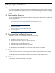
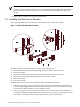
Figure 1-3 Slide Brackets 1 2 The following list corresponds to the callouts shown in Figure 1-3: 1. Flat surface of a slide bracket that mounts to the ProCurve switch chassis 2. Thumb screw (two for each slide bracket) that secures the ProCurve switch to the rack mount brackets 1.8 Installation Preparations Prepare for the installation as follows: 1. Ensure that the cluster is shut down and powered off so that you can perform the installation. 2.
2 Installing and Using the ProCurve 1U Rack Mount Brackets 2.1 Identifying the Installation Location The installation location is dependent on the configuration rules for your XC Cluster upgrade bundle. See Section 1.2 for information on where you can obtain XC documentation resources. An upgrade bundle consists of a number of different components, such as ProLiant DL380 servers, ProCurve switches, and cables of predetermined length.
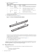
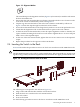
Note: To make assembly easier, insert the first screw through the slide bracket hole and hold it in place with the screwdriver tip before you place the slide bracket against the side of the switch. 3. Repeat steps 1 and 2 for the opposite slide bracket. 2.3 Installing the Rack Mount Brackets This section describes how to mount the rack mount brackets to the rack columns. Figure 2-2 Attach the Rack Mount Brackets 4 2 1 3 5 6 The following list corresponds with the callouts shown in Figure 2-2. 1.
Figure 2-3 Alignment Washer The raised bumps on the alignment washers (Figure 2-3) face inward, toward the rack mount bracket’s threaded insert. Ensure that the rack mount bracket’s rear flange is aligned with the correct location on the rack’s front column as indicated by callout 3 in Figure 2-2. Clip the cage nuts into the holes in the rack’s front column as indicated by callout 4 in Figure 2-2. Push the clips through from the back of the column.
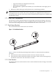
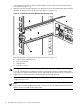
1. 2. Lift and align the switch so that the slide brackets are level with the rack mount brackets (see callout 1 in Figure 2-4. Slide the switch in until the thumb screws (quantity four) on the slide bracket align with the thread holes in the rack mount bracket (see callout 1 in Figure 2-5). Figure 2-5 Thumb Screw on the Slide Bracket (Quantity Four) 2 4 3 1 The following list corresponds to the callouts shown in Figure 2-5. 1. Thumb screw (quantity four) 2. Rear rack column 3. Slide bracket 4.
3 Cabling and Power Follow the installation instructions for the XC cluster upgrade bundle with which this kit was shipped. See Section 1.2 (page 3) for information on where you can obtain XC documentation resources. It is important that you connect the servers to the correct network cables and interconnect cables, and that you apply power in the correct sequence. For applications other than the XC series, see the cabling and power-on instructions shipped with your server.
4 Removing a Switch for Servicing Bring the cluster to an appropriate state for switch component removal and put the rack into a safe and stable state for component removal. You must ensure that you can easily reach the switch and handle it safely. To remove a switch from a rack, follow these steps: 1. 2. 3. At the rack power distribution unit, power off the circuit to which the ProCurve Switch is connected. Disconnect the switches power cable.
*5991-7451* Printed in the US