HP Cluster Platform ProCurve 3500 Series CX4 Cable Management Bracket Installation Guide HP Part Number: 5991-7985 Published: July 2007
© Copyright 2007 Hewlett-Packard Development Company, L.P. The information contained herein is subject to change without notice. The only warranties for HP products and services are set forth in the express warranty statements accompanying such products and services. Nothing herein should be construed as constituting an additional warranty. HP shall not be liable for technical or editorial errors or omissions contained herein. Printed in the U.S.A.
Table of Contents 1 Preparing for Installation................................................................................................6 1.1 Audience...........................................................................................................................................6 1.2 Documentation Resources.................................................................................................................6 1.3 Kit Description......................................................
List of Figures 1-1 1-2 1-3 2-1 2-2 2-3 2-4 Cable Management Bracket............................................................................................................6 3.5 Inch Fabric Strap........................................................................................................................7 5.0 Inch Fabric Strap........................................................................................................................7 Cable Management Bracket Orientation...........
List of Tables 1-1 Fasteners..........................................................................................................................................
1 Preparing for Installation 1.1 Audience This guide is intended for HP service representatives and other persons trained to install hardware options in HP 10000 Series Racks. Such persons are expected to understand the hazards of working in this environment and to take suitable precautions to minimize danger to themselves and others. 1.
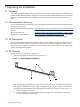
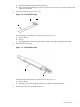
3. 4. • Cable management bracket mounting holes Five inch strap mounting hole used to clip the five inch strap for vertical routing of the cables in the cabinet. Two 3.5 inch fabric straps (Figure 1-2) Figure 1-2 3.5 Inch Fabric Strap 2 3 1 The following list describes the callouts shown in Figure 1-2: 1. Fabric closure 2. D-ring 3. Metal grommet used to mount the fabric strap to the cable management bracket • One 5.0 inch fabric strap Figure 1-3 5.
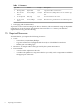
Table 1-1 Fasteners • Qty. Size Format Torque Description 2 M6 Cage Nuts Square Nut N/A Cage nut for M6 x 16 mm screw. 2 M6 x 16 mm Screws Screw, Phillips 30 in/lb Machine screw, Phillips drive. For use with the cage nut. 4 10–32 Clip Nut Nut, Clip N/A For use with the 10–32 screws. 4 10–32 x 0.625 Screws Screw, Phillips 30 in/lb Machine screw, pan-head. For use with the clip nut. Packaging and documentation.
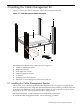
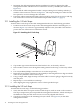
2 Installing the Cable Management Kit Figure 2-1 shows the correct orientation of the cable management bracket. Figure 2-1 Cable Management Bracket Orientation 3 1 2 5 4 6 7 The following list describes the callouts shown in Figure 2-1: 1. ProCurve 3500 Series switch 2. Right side slide rail 3. Front right rack column 4. Cable management bracket 5. yl module 6. Mounting screw and cage nut 7. Direction of view looking in from the front of the rack 2.
1. 2. 3. Determine the cable management bracket installation location by aligning the cable management bracket with the ProCurve 3500 Series switch's yl module (see callout 5 in Figure 2-1). Ensure that the cable management bracket's strap mounting face is lined up with the yl module's CX4 connectors as shown in Figure 2-1. The strap mounting face radius' should face upward so as not to damage the CX4 cables. Fasten the cable management bracket to the front rail by using four 10–32 screws and clip nuts.
Figure 2-3 Attaching the 5.0 Inch Strap 1 The vertical routing of the cable bundle depends on the HP Cluster Platform configuration. Regardless, the 5.0 inch strap provides the vertical routing and strain relief for the cables in the cabinet, as shown in Figure 2-4. Figure 2-4 Cable Routing Example 2.2 Removing the Switch for Servicing Bring the component to an appropriate state for removal, and put the rack cabinet into a safe and stable state for component removal.
*5991-7985* Printed in the US