
ProCurve 3500 Series CX4 Cable Management Bracket Installation Guide


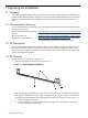

1. Determine the cable management bracket installation location by aligning the cable
management bracket with the ProCurve 3500 Series switch's yl module (see callout 5 in
Figure 2-1).
2. Ensure that the cable management bracket's strap mounting face is lined up with the yl
module's CX4 connectors as shown in Figure 2-1. The strap mounting face radius' should
face upward so as not to damage the CX4 cables.
3. Fasten the cable management bracket to the front rail by using four 10–32 screws and clip
nuts. Fasten the screws to the recommended torque listed in Table 1-1 (page 8).
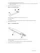
2.1.1 Installing the 3.5 Inch Straps
To attach the 3.5 inch straps to the cable management bracket, use the following procedure:
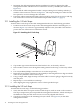
1. Position one of the 3.5 inch straps on the cable management bracket's mounting face, as
shown in Figure 2-2, so that it is approximately adjacent to the yl module CX4 connector
ports in the rear of the ProCurve 3500 Series switch.
Figure 2-2 Attaching the 3.5 Inch Strap
2
3
1
2. Clip an M6 cage nut into the bottom of the bracket's slot, as shown by callout 1.
3. Insert an M6 x 16-mm screw through the metal grommet in the strap, as shown by callout
2.
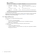
4. Use a #2 (medium) Phillips screwdriver to secure the strap loosely.
5. Rotate the strap (callout 3) and move it horizontally in the elongated slot to align it with the
center of the yl module's CX4 connector port.
6. Using a sample cable, align the strap so that the cable's connector (plug) is aligned correctly
with the ports.
7. Repeat steps 1–6 to install the second strap.
8. After aligning the straps, tighten the screws to their specified torque.
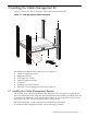
2.1.2 Installing the 5.0 Inch Strap
To install the five inch strap, use the following procedure:
1. Verify that the cables are square and level with the ports, with no strain on the connector.
This step is important to prevent possible electromagnetic interference, which can leak past
the EMI seals if the port and connector are not correctly aligned and secured.
2. Clip the five inch strap to the mounting hole (see callout 1 in Figure 2-3) on the cable
management bracket.
10 Installing the Cable Management Kit