HP Cluster Platform ProCurve 6400 CX4 Cable Management Kit Installation Guide HP Part Number: 5991-7987 Published: July 2007
© Copyright 2007 Hewlett-Packard Development Company, L.P. The information contained herein is subject to change without notice. The only warranties for HP products and services are set forth in the express warranty statements accompanying such products and services. Nothing herein should be construed as constituting an additional warranty. HP shall not be liable for technical or editorial errors or omissions contained herein. Printed in the U.S.A.
Table of Contents 1 Preparing for Installation................................................................................................6 1.1 Audience...........................................................................................................................................6 1.2 Documentation Resources.................................................................................................................6 1.3 Kit Description......................................................
List of Figures 1-1 1-2 1-3 2-1 2-2 2-3 2-4 2-5 2-6 Cable Management Bracket............................................................................................................6 3.5–Inch Fabric Strap.......................................................................................................................7 5–Inch Fabric Strap..........................................................................................................................
List of Tables 1-1 Fasteners..........................................................................................................................................
1 Preparing for Installation 1.1 Audience This document is intended for HP service representatives and other persons trained to install hardware options in HP 10000 Series Racks. Such persons are expected to understand the hazards of working in this environment and to take suitable precautions to minimize danger to themselves and others. 1.
columns of the HP 10000 Series Rack. The following list describes the callouts shown in Figure 1-1: 1. Cable management bracket (two brackets of the same type are included in each kit). 2. The mounting face, which contains three mounting slots. Attach the 3.5–inch fabric straps to this part of the bracket. 3. Cable management bracket mounting holes. 4. 5-inch strap mounting hole used to clip the 5-inch strap for vertical routing of the cables in the cabinet. • Eight 3.
Table 1-1 Fasteners • Qty. Size Format Torque Description 8 M6 Cage Nuts Square Nut N/A Cage nut for M6 x 16 mm screw. 8 M6 x 16 mm Screws Phillips (Posidrive) 30 in/lb Machine screw, Phillips drive. For use with the cage nut. 8 10–32 Nuts Nut, Clip N/A For use with the 10–32 screws. 8 10–32 x 0.625 Screws Phillips (Posidrive) 30 in/lb Machine screw, pan-head. For use with the clip nut. Packaging and documentation.
2 Installing the Cable Management Kit Chapter 2 includes the following sections: • Installing the Cable Management Bracket in the Front of the Rack (Section 2.1) • Installing the Cable Management Bracket in the Rear of the Rack (Section 2.2) • Installing the 3.5–Inch Straps (Section 2.3) • Installing the 5–Inch Straps (Section 2.4) • Cable Routing Examples (Section 2.5) 2.
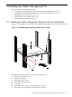
The location of the cable management bracket depends on the rack position occupied by the HP ProCurve 6400cl switch. Align the cable management bracket with the cl module in the rear of the HP ProCurve 6400cl switch. The bracket occupies 1U (1.75 inches) of rack space and is mounted on the front of the HP 10000 Series Rack facing inward as shown in Figure 2-1. For more information, consult your HP Cluster Platform documentation. To install the cable management bracket, follow these steps: 1.
The following list describes the callouts shown in Figure 2-2: 1. HP ProCurve 6400cl switch 2. HP ProCurve 1U rack mount slide rail 3. Thumb screw 4. Rack right column 5. Cable management bracket 6. Top and bottom HP ProCurve 1U slide rail kit mounting screws 7. Direction of view looking in from the rear of the rack The location of the cable management bracket depends on the rack position occupied by the HP ProCurve 6400cl switch.
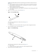
1. Position one of the 3.5–inch straps on the cable management bracket's mounting face, as shown in Figure 2-3, so that it is approximately adjacent to the CX4 connector ports in the cl module in the rear of the HP ProCurve 6400cl switch, and also for the CX4 connector ports on the front of the HP ProCurve 6400cl switch. Figure 2-3 Attaching the 3.5–Inch Strap 2 3 1 2. 3. 4. 5. 6. 7. 8. Clip an M6 cage nut into the bottom of the bracket's slot, as shown by callout 1 in Figure 2-3.
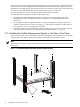
2. Clip the 5–inch strap to the mounting hole (see callout 1 in Figure 2-4) on the cable management bracket. Figure 2-4 Attaching the 5–Inch Strap 1 2.5 Cable Routing Examples The vertical routing of the cable bundles depend on the HP Cluster Platform configuration. Regardless, the 5–inch straps provide the vertical routing and strain relief for the cables in the cabinet, as shown in Figure 2-5 and Figure 2-6. Figure 2-5 Cable Routing Example – Front of Rack 2.
Figure 2-6 Cable Routing Example – Rear of Rack 1 14 Installing the Cable Management Kit
3 Removing the Switch for Servicing Bring the component to an appropriate state for removal, and put the rack cabinet into a safe and stable state for component removal. You must ensure that you can reach the component easily and handle it safely. Remove the unit as follows: 1. Switch off the power supply from the rack's power distribution unit and disconnect the power cable. 2. Disconnect and remove each network cable until all of the networking ports are unplugged. 3.
*5991-7987* Printed in the US