HP Cluster Platform Tab Mount Cable Management Bracket Installation Guide Part Number: AA-RWT1A-TE March 2005 Revision/Update Information: This is a new document. This document describes how to attach a tab mount cable management bracket to an HP 10000 and 15000 series racks. The bracket is designed to align and support the cables that lead from a cluster’s system interconnect to the PCI card installed in each cluster node (server).
© Copyright 2005 Hewlett-Packard Development Company, L.P. The information contained herein is subject to change without notice. The only warranties for HP products and services are set forth in the express warranty statements accompanying such products and services. Nothing herein should be construed as constituting an additional warranty. HP shall not be liable for technical or editorial errors or omissions contained herein. Printed in the U.S.A.
1 Preparing for Installation 1.1 Audience This guide is intended for HP service representatives and other persons trained to install hardware options in the HP 10000 and 15000 series racks. Such persons are expected to understand the hazards of working in this environment and to take suitable precautions to minimize danger to themselves and others. 1.
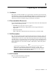
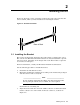
Figure 1-1: Cable Management Bracket X Y Z [ The bracket can be used in several models of the HP Cluster Platform and might be adaptable for other cable management applications (consult your hardware installation documentation). The following bracket features are called out in the illustration: • 1. Mounting holes, which you use to attach the bracket to the rack. 2. The mounting face, which contains three mounting slots. You attach cable management straps to this part of the bracket. 3.
• Packaging and documentation. To prevent screws from becoming loose because of vibration, HP recommends that you use an adjustable torque driver set to the torque specifications given in Table 1-1. Contact your HP sales representative if any parts are missing. 1.5 Required Resources To install the kit, you require the following resources: • Tools: - Screwdriver, Torx (T15). - Screwdriver, #2 (medium) Phillips. - Cage-nut insertion tool (shipped with the rack) or a flat-bladed screwdriver.
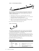
2 Installing the Kit Figure 2-1 shows the correct orientation of the bracket, but it does not show the server’s rail kit, which you must install before mounting the bracket. Figure 2-1: Bracket Orientation Rear of Rack 2.1 Installing the Bracket The location of the bracket depends on the rack position occupied by the server. The servers in an HP Cluster Platform solution are always installed in a specific rack (U) location, depending on the design of the rack. The bracket occupies 1U (1.
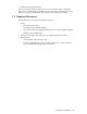
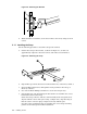
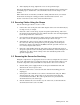
Figure 2-2: Attaching the Bracket X Z Y 29 4. With a Torx T15 screwdriver, secure the bracket to the rail by using two 6-32 screws. 2.1.1 Installing the Strap Use the following procedure to attach the strap to the bracket: 1. Position the strap on the bracket, as shown in Figure 2-3, so that it is approximately adjacent to the interconnect card in the server’s PCI slot. Figure 2-3: Attaching the strap 2 Y [ X 1 3 Z 2.
6. After aligning the strap, tighten the screw to its specified torque. Repeat the installation procedure for subsequent bracket kits, using a marker pen or masking tape to transfer the correct horizontal location of the strap to each bracket. When all brackets are installed, consult the cabling instructions for your cluster model before starting the cabling procedure described in Section 2.2. (See Section 1.2 for the location of the cluster documentation.) 2.