
Tab Mount Cable Management Bracket Installation Guide

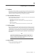
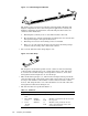
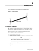
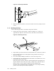

Figure 1-1: Cable Management Bracket
Y
X
Z
[
The bracket can be used in several mode
ls of the HP Cluster Platform and
mightbeadaptableforothercablema
nagement applications (consult your
hardware installation document
ation). The following bracket features are
called out in the illustration:
1. Mounting holes, which you use to attach the bracket to the rack.
2. The mounting face, which contain
s three mounting slots. You attach cable
management straps to this part of
the bracket.
3. Mounting screw. Two 6-32 mounting screws are included.
4. Holes, one at each end of the bracket, for snap-on hook-and-loop straps
used for vertical routing of the cables in the cabinet.
• Two 3.5-inch (889-mm) fabric straps (Figure 1-2).
Figure 1-2: Fabric Strap
2
1
3
The strap has a hook-and-loop fabric closure (callout 1) and a metal D-ring
(callout 2) that is designed to secure a single interconnect cable. The strap
is secured to the bracket through a metalgrommet(callout3). Yourcable
management solution might use one or both straps.
• Three hook-and-loop
straps(5,8,and12inchesinlength).Theseprovidethe
vertical routing of
thecablesinthecabinet.Thevarioussizesareusedtoallow
forlargercablebun
dles as the number of cables and servers in the cabinet
increase. The stra
ps mount to one of the small holes on each end of the cable
management bracke
t shown in Figure 1-1.
• The fasteners that are specified in Table 1-1.
Table 1-1: Fasteners
Qty. Size
Format Torque
Description
2
M6 cage
nuts
Square nut N/A Cage nut for M6 x 16mm screw.
2
M6 x 16mm
screws
Phillips
(Posidrive)
30
in/lb
Machine screw,
Torx head. For use with
thecagenut.
26-32x
.25-inch
screws
Torx T15
30
in/lb
Machine screw, pan-head. For use
with a threade
d insert in the cable
management bracket.
1-2 Preparing for Installation