
The Network and InfiniBand Cable Management Harness Installation Guide (572559-doc)


2 Installing the Network and InfiniBand Cable Management
Harness
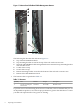
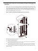
Figure 2-1 shows the correct orientation of the network and InfiniBand cable management harness.
The location of the network and InfiniBand cable management harness depends on the location
of the components and cables in the rack. For example, for HP BladeSystem configurations, the
network and InfiniBand cable management harness is installed to the right side of the rack
(looking in from the rear of the rack) to allow access to HP c-Class BladeSystem components in
the rear of a HP BladeSystem c-Class enclosure.
Figure 2-1 Network and InfiniBand Cable Management Harness Orientation
4
5
3
2
1
The following list describes the callouts shown in Figure 2-1:
1. M6 cage nut (installed at factory)
2. M6 screw (installed at factory)
3. Top and bottom mounting bracket locations used to mount the network and InfiniBand
cable management harness in the rack's rear center
4. Top and bottom mounting bracket locations used to mount the network and InfiniBand
cable management harness in the rack's right side (looking in from the rear of the rack)
To mount the network and InfiniBand cable management harness in the HP 10000 Series rack,
follow these steps:
11