HP XC3000 Cluster HP XC Interconnect xx3020 Cabinet Kit Installation Guide Part Number: AA-RVBLA-TE January 2004 Revision/Update Information: This is a new manual. This document describes how to install the HP XC Interconnect xx3020 Cabinet Kit into an HP Model 10642 rack.
© Copyright 2004 Hewlett-Packard Development Company, L.P. The information contained herein is subject to change without notice. The only warranties for HP products and services are set forth in the express warranty statements accompanying such products and services. Nothing herein should be construed as constituting an additional warranty. HP shall not be liable for technical or editorial errors or omissions contained herein.
1 HP XC Interconnect xx3020 Cabinet Kit Install Guide 1 Audience HP service representatives and other persons trained to install hardware mounting options and system components in HP 10000-series racks. Such persons are expected to understand the hazards of working in this environment and to take suitable precautions to minimize danger to themselves and to others.
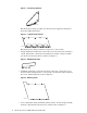
Figure 1: Left Bracket Retainer ZK-2046 This bracket has a flange by which you attach it to the support track. Figure 2 shows the right-hand bracket. Figure 2: Right Bracket Retainer ZK-2067 This bracket has a flange by which you attach it to a rack column. • A single hold-down bracket that connects the rear of the interconnect chassis to a track. The bracket contains two threaded inserts and has a flange by which you attach it to the interconnect’s chassis. See Figure 3.
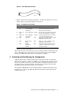
Figure 5: Cable Management Strap ZK-2070 • Table 1 specifies the fasteners included in the kit. You will also reuse some fasteners that are provided with the interconnect. Table 1: Installation Kit Fasteners • Qty. Dimension Type Torque Description 2 6/32 x .375 Machine in screw, Phillips (Posidrive) 30 in/lb Small pan-head screw used to attach the hold-down bracket to the interconnect chassis.
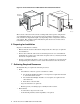
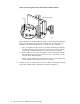
Figure 6: HP XC Interconnect xx3020 Cabinet Kit and Rack Orientation Interconnect Interconnect Rear of the Rack Duct Duct Front of the Rack Air Intake Rails The location of the interconnect in the rack depends on the specific configuration of your XC3000 Cluster. Up to four interconnects might be installed in a single rack, and their rack positions might vary depending on the configuration rules for your system.
_____________________ Caution ____________________ Always install components into a rack working from the bottom of the rack upwards. An HP XC3000 interconnect building block (IBB) rack might contain up to four HP XC Interconnect xx3020 units. The HP XC Interconnect xx3020 weighs approximately 32 kg (70 lb) when fully populated with port cards.
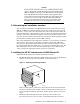
the interconnect’s original bracket. The correct orientation of the bracket is with its flange facing inward toward the interconnect’s ports, as shown in Figure 8. Figure 8: Mounting the Left-Hand (Angled) Bracket on the Interconnect Chassis ZK-2043 3. Mount the right-hand bracket retainer to the interconnect’s chassis. Use five of the countersunk flat-head screws from the interconnect’s original bracket. The correct orientation of the bracket is with its flange facing outward, as shown in Figure 9.
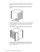
Figure 10: Orientation of the Tracks Rear of the Rack 1 ZK-2045 Figure 11 shows how the mounting holes on the end of the track (callout 1) align with the square mounting holes on the face of the rack column. Figure 11: Inserting the Cage Nuts 2 1 8 3 ZK-2040 Clip two cage nuts (callout 3) into the back of the rack column, using the square mounting holes shown by callout 2. Repeat this operation for each track, using a total of eight cage nuts.
Figure 12: Securing the Air Duct to the Front Left Rack Column Front of the Rack 1 ZK-2041 Figure 12 shows the track installed at position 8. The lowest threaded insert in the air duct aligns with the bottom mounting hole at rack position 10. Starting at the bottom mounting hole, secure the air duct as follows: 6. 8 a. Place an alignment washer on the rack column mounting hole.
Figure 13: Securing the Air Duct’s Rear Bracket to the Rear Right Rack Column Rear of the Rack (Right Column) X Air Duct Y U-Nut ZK-2044 Use the following procedure to attach the air duct: a. Prepare the front bracket, which supports the blanking plate that you install in step 9 of the installation procedure. This bracket is indicated by callout 1 in Figure 13. Clip a U-nut over each of the three holes in the bracket as shown in the magnified section of the drawing.
Table 2: Rack Positions for Securing the Right Bracket. b. Rack Position Mounting Hole Example, using T=8 T+1 Top (3) 9 Top T+3 Top (3) 11 Top T+7 Bottom (1) 15 Bottom T+9 Bottom (1) 17 Bottom Working from the rear of the rack, insert the interconnect into the rack and slide it along the tracks until the right bracket makes contact with the rack column, as shown in Figure 14.
Figure 15: Securing the Hold-Down Bracket 6/32 x .375 ZK-2074 Front of the Rack Use the following procedure to fasten the hold-down bracket: 9. a. The hold-down bracket has two threaded inserts that align with two holes in the right-hand track. Temporarily place the bracket on the outside face of the track and align it with the holes in the track. This enables you to identify two recessed screws in the interconnect chassis. Put the bracket aside and remove the screws from the chassis.
Figure 16: Attaching the Blanking Plate Front of the Rack ZK-2075 _______________________ Note _______________________ Before installing the blanking plate, connect a power cable from the power distribution bars to the power inlet at the rear of the interconnect. Follow the configuration guidelines for your system when selecting a power outlet.
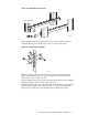
c. Use three M6 x 16 mm screws to secure the right side of the plate to each of the cage nuts in the right-hand rack column. 10. Attach the cable management straps as shown in Figure 17. Figure 17: Attaching the Cable Management Straps M5 x 10 mm ZK-2076 M6 x 16 mm Rear of the Rack The interconnect chassis has 16 slots, some of which might contain 8-port cards. There is a 2-port control card at the top. Each cable management strap provides support for 24 fibre-optic cables.
10 Cabling and Power Ensure that the rack is powered off by checking its power distribution unit (PDU) breakers. Starting at the back of the rack, insert a 4-foot long power distribution cord in the adjacent power strip. Feed the power cord underneath the interconnect chassis to the front of the rack, and connect it to the chassis power inlet. The HP XC Interconnect xx3020 does not have an independent power breaker and will power up when power is applied from the rack’s PDU.
7. _____________________ Warning _____________________ A fully loaded interconnect weighs approximately 32 kg (70 lb). This removal step requires at least two people suitably equipped and trained to lift the interconnect out of the rack. If you are removing a switch from the topmost position in a rack, use a stable, elevated work platform or equivalent. Slide the interconnect out of the rear of the rack.