
XC3000 Cluster HP XC Interconnect xx3020 Cabinet Kit Installation Guide
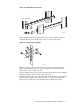
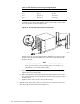
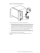


Figure 13: Securing the Air Duct’s Rear Bracket to the Rear Right Rack
Column
Rear of the Rack
(Right Column)
Air Duct
X
Y
ZK-2044
U-Nut
Use the following procedure to attach the air duct:
a. Prepare the front bracket, which supports the blanking plate that you
install in step 9 of the installation procedure. This bracket is indicated by
callout 1 in Figure 13. Clip a U-nut over each of the three holes in the
bracket as shown in the magnified section of the drawing. Ensure that
the threaded part of the nut faces toward the rear of the rack.
b. Align the duct so that the three holes in its rear bracket align with three
square holes in the right rack column. Ensure that the duct is level, and
mark the mounting holes on the rack column with tape or a marker pen.
c. Clip three cage nuts to the inside of the rack column at the marked
locations.
d. Insert an M6 x 16 mm screw through the topmost hole in the duct’s rear
bracket and secure it loosely a few turns.
e. Repeat steps C and D for the remaining two holes in the bracket.
f. Tighten all six screws that secure the air duct to the front and rear
rack columns.
7.
_____________________ Warning _____________________
A fully loaded interconnect weighs approximately 32 kg (70 lb). This
installation step requires at least two people suitably equipped and
trained to lift the interconnect into the rack. If you are installing a
switch into the topmost position in a rack, use a stable, elevated
work platform or equivalent.
Secure the front of the interconnect by using the following procedure:
a. Insert four cage nuts into the back of square mounting holes in the right
rack column at the positions defined in Table 2, where T is the rack
position at which the track is currently mounted.
HP XC Interconnect xx3020 Cabinet Kit Install Guide 9