
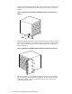
XC3000 Cluster HP XC Interconnect xx3020 Cabinet Kit Installation Guide


10 Cabling and Power
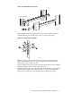
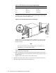
Ensure that the rack is powered off by checking its power distribution unit (PDU)
breakers. Starting at the back of the rack, insert a 4-foot long power distribution
cord in the adjacent power strip. Feed the power cord underneath the interconnect
chassis to the front of the rack, and connect it to the chassis power inlet.
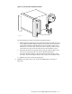
The HP XC Interconnect xx3020 does not have an independent power breaker and
will power up when power is applied from the rack’s PDU. Do not power up the rack
until you have consulted the hardware and software documentation for your cluster.
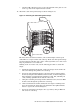
Follow the cabling sequence instructions for the fibre-optic cables as described
in your cluster documentation. The cabling instructions are designed to ensure
that the correct number of cables are grouped and bound together, then routed
along the rack’s cable management system. It is important that you use the cable
management guidelines for the specific installation that you are configuring and
that you maintain the correct maximum bend radius for the fiber-optic cables.
Bending a cable beyond its limit can cause internal damage to the glass core.
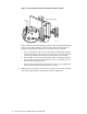
11 Removing the HP XC Interconnect xx3020 from the Rack
To remove the HP XC Interconnect xx3020 from the rack, use the following
procedure. You remove the interconnect from the rear of the rack, which might
have limited working room depending on how close the rack is located to walls
or other racks. Take note of the safety warning concerning the safe handling of
the interconnect.
_______________________ Warning _______________________
Before beginning the removal procedure, power off the interconnect by
using the breaker switch at the PDU.
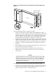
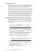
1. Prepare a suitable work surface and clear a pathway for removal of the
interconnect. Ensure that there are no cables or other obstructions underfoot.
2. At the front of the rack, remove the six screws holding the blanking plate, then
disconnect the interconnect’s power supply cable.
3. At the rear of the rack, disconnect the fiber-optic cables after first ensuring
that the cables are properly labelled for their appropriate ports. This is
important if you are planning to replace a defective interconnect.
Remove the cables from the cable management straps, and route them
carefully out of the way of the interconnect’s removal path.
_______________________ Note _______________________
Observe the maximum bend radius for fiber-optic cables. Bending
the cables too much can cause the glass core to break.
4. Working at the front of the rack, remove the two small screws that secure the
interconnect chassis to the hold-down bracket on the right-hand track.
5. Working at the rear of the rack, remove the two screws that secure the
left-hand (angled) bracket to the track.
6. Working at the rear of the rack, remove the four screws that secure the
right-hand bracket to the right rack column.
14 HP XC Interconnect xx3020 Cabinet Kit Install Guide