
XC3000 Cluster HP XC Interconnect xx3020 Cabinet Kit Installation Guide

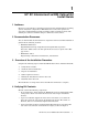
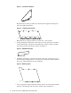
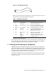
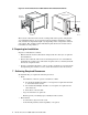
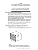
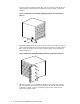
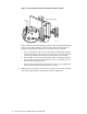

Figure 5: Cable Management Strap
ZK-2070
• Table 1 specifies the fasteners included in the kit. You will also reuse some
fasteners that are provided with the interconnect.
Table 1: Installation Kit Fasteners
Qty.
Dimension Type Torque Description
2
6/32 x .375
in
Machine
screw, Phillips
(Posidrive)
30 in/lb Small pan-head screw used to
attach the hold-down bracket to
the interconnect chassis.
11
M5 x 10
mm
Screw, Torx T25 30 in/lb Torx screw used only for parts that
provide threaded holes or inserts.
25
M6 x 16
mm
Screw, Phillips
(Posidrive)
30 in/lb Longer pan-head screw used with
cage nut M6 and M6 U-nut.
22
M6 Cage nut N/A Clips onto the rack columns. Used
with M6 pan-head screw.
3
M6 Sheet metal
U-nut
N/A Clips on to rack columns. Used
with M6 pan-head screw.
3
M6 Square
alignment
washer
N/A Converts square holes in the rack
columns to round holes for the
pan-head screws.
• Packaging and documentation.
To prevent screws from becoming loose due to vibration, HP recommends that you
use an adjustable torque driver set to the torque specifications given in Table 1.
Contact your HP sales representative if any parts are missing.
5 Orienting and Positioning the Components
A HP XC Interconnect xx3020 Cabinet Kit is required to install every HP XC
Interconnect xx3020 in a cluster. In addition to securing the interconnect chassis
in the rack, the kit contains an air duct that directs ambient-temperature air to
the interconnect’s cooling fan module. You must ensure that the duct remains
unobstructed when the interconnects are powered up.
You install the HP XC Interconnect xx3020 with its communication ports facing
toward the rear of the rack. Figure 6 shows the orientation of the interconnect
relative to the rack.
HP XC Interconnect xx3020 Cabinet Kit Install Guide 3