XC3000 Cluster Quad Bracket Kit Installation Guide Part Number: AA-RV4HA-TE December 2003 This document describes how to install the quad bracket kit into an HP Model 10642 rack.
© Copyright 2003 Hewlett-Packard Development Company, L.P. The information contained herein is subject to change without notice. The only warranties for HP products and services are set forth in the express warranty statements accompanying such products and services. Nothing herein should be construed as constituting an additional warranty. HP shall not be liable for technical or editorial errors or omissions contained herein. Printed in the U.S.A.
1 Overview This rack kit consists of a four-slot (quad) bracket that is designed to mount to the columns of the HP Model 10642 rack. This is the standard high-density rack model used for the XC-series cluster. The quad bracket can accept up to four 1U server systems. Each server requires a mounting slide that inserts into a track in the quad bracket. No tools are required to install the quad bracket or the slides.
• One left-hand quad bracket (attaches to the rack columns). • One right-hand quad bracket (attaches to the rack columns). • Four left-hand mounting slides (attaches to the server chassis). • Four right-hand mounting slides (attaches to the server chassis). • Packaging and documentation. Contact your HP sales representative if any parts are missing. 6 Orienting the Components All orientation instructions are relative to the front of the rack. 6.
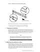
Figure 1-2: Orientation of the Left-Hand Mounting Slide 2 1 Front of the Switch The following mounting features are referenced in the installation procedure: 1. The cut-out (hole) located at the rear of the mounting slide. 2. The keyhole slots for attaching the slide to the server chassis. 7 Preparing for Installation No tools are required to install the quad bracket and mounting slides.
The quad bracket’s installation location is dependent on the configuration rules for your XC cluster upgrade bundle. (You can obtain the documentation from the locations specified in Section 3.) An upgrade bundle consists of a number of different components, such as servers, Ethernet switches, and cables of predetermined length. Each component must occupy a specific rack location so that the inter-component cabling is correct.
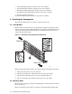
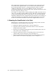
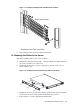
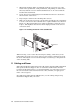
Figure 1-3: Installing the Right-Hand Quad Bracket in the Rack Right-Hand Bracket 3 2 Viewed from the Front of the Rack 6. Repeat this procedure for the left-hand quad bracket. 10 Mounting the Slides to the Server Attach the mounting slides to the server as follows: 1. Identify the left-hand mounting slide, as shown in Figure 1-2. Ensure that the cut-out is toward the rear of the server. 2. Position the keyhole slots over the raised posts in the side of the case, as shown in Figure 1-4.
5. When both mounting slides are installed, insert the server into one of the tracks in the quad bracket. Using both hands, and pushing on either side of the bezel, slide the server in until its thumbscrews are in contact with the bracket’s threaded inserts. 6. Secure the server by tightening the two thumbscrews that are attached to the front bezel of the server. 7. Repeat steps 5 and 6 for the remaining three servers. 8. Slide each of the four servers into a track in the quad bracket.