
XC6000 Cluster Cable Management Tray Installation Guide


• The fasteners specified in Table 1-1.
Table 1-1: cable management tray Fasteners
Qty. Size
Type Torque Description
3
M5 X 0.8
10 mm
Phillips
(Posidrive)
30 in-lb Machine screw, pan-head
1
M6 Slotted 30 in-lb Screw, captive
• Packaging and documentation.
To prevent screws from becoming loose due to vibration, HP recommends that you
use an adjustable torque driver set to the torque specifications given in Table 1-1.
Contact your HP sales representative if any parts are missing.
5 Orienting the Components
A cable management tray is required for every server that has a PCI interconnect
card for the HP XC Interconnect xx6020. The PCI cards provide a connection
port for the interconnect cable. The copper cable is heavy and has a limited bend
radius. The cable management tray supports the cable, providing strain relief for
the PCI port and ensuring a good connection. It also ensures the correct bend
radius for the cable.
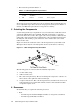
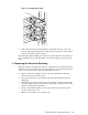
Figure 1-1 shows the orientation of the cable management tray toward the rack.
This figure shows only the 5-inch strap that attaches to the surface of the tray.
Figure 1-1: cable management tray Orientation
xc-cmt-01
2
1
4
3
To Rear of the Rack
The following parts are referenced in the installation procedure:
1. A 5-inch fabric strap.
2. A M5 x 10 mm screw.
3. The cable management tray. The two mounting holes adjacent to callout 3 are
the locations of the eight-inch and 13-inch straps.
4. A captive slotted screw. The cable management tray installs on the end of each
rack-mounted server’s rail kit. The rail kit contains a threaded insert which
accepts this captive screw.
6 Resources
To install the kit, you require the following resources:
• Tools:
- A 6-inch long #2 (medium) Phillips (Posidrive or cross-point) screwdriver.
- A 6-inch long flat-bladed screwdriver.
1-2 Cable Management Tray Installation Guide