
Gigabit Ethernet Interconnect Guide

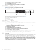


The rear panel has cooling vents, which must not be obstructed for proper switch operation.
Note:
The switch is installed in the rack with the back side facing the front of the rack.
3.3 HP ProCurve 2800 Series LEDs and Buttons
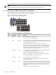
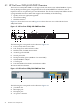
The front panel of the ProCurve 2800 series have eight types of LEDs, as described in Figure 3-5.
The rear panel of the ProCurve 2800 series have no LEDs.
Figure 3-5 HP ProCurve 2800 Series LEDs
1
2
3
4
5
6
7
8
Table 3-1 HP ProCurve 2800 Series LED Identification
MeaningStateDescriptionItem
On = The switch is receiving power.GreenPower1
Off = The switch is not receiving power.
On = The switch has encountered a fatal hardware failure or has failed its
self-test. This LED comes on briefly after the switch is powered on or reset,
at the beginning of switch self test.
OrangeFault2
Off = Indicates that there are no fault conditions on the switch.
Blinking
1
= A fault has occurred on the switch, one of the switch ports,
or the fan. The status LED for the component with the fault will blink
simultaneously. If just the Fault LED is blinking, the switch could be
attached to an RPS but not receiving power.
On = An HP ProCurve EPS/RPS unit is connected and operating correctly.
The EPS/RPS could be powering the unit.
GreenRPS Status3
Off = The EPS/RPS is not connected or is not powered.
Blinking
1
= The EPS/RPS is connected but may be powering another
switch or the EPS/RPS has experienced a fault.
On = The cooling fan is working properly.GreenFan Status4
Off = One of the unit’s fans has failed. The switch Fault LED will be
blinking simultaneously.
On = The switch self test and initialization are in progress after the switch
has been power cycled or reset . The switch is not operational until this
GreenSelf-Test5
LED goes off. The test LED also comes on briefly when you “hot swap” a
mini-GBIC into the switch; the mini-GBIC is self tested when it is hot
swapped.
Off = The switch is not undergoing self test.
26 HP ProCurve 2800 Series