
Gigabit Ethernet Interconnect Guide
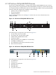
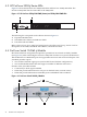

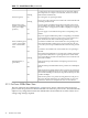
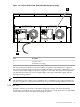

Table 5-1 Switch Chassis LEDs (continued)
MeaningStateLEDs
A component of the switch has failed its self test. The Status LED for
that component, for example a switch module, and the switch Fault
LED will flash simultaneously.Flashing
The cooling fans are operating normally.OnStatus/Fan (green)
One or more of the cooling fans have failed. The switch Fault LED will
be flashing simultaneously.Flashing
A power supply is installed in the position in the back of the switch
corresponding to the number, and the supply is plugged in to an active
On
Status/Power (green -
numbers corresponding
AC power source. As shipped, the switch has a single power supply in
position 1.
to the power supply
positions)
A power supply is not installed in the position corresponding to the
number.Off
The power supply installed in the position corresponding to the number
is not plugged in to an active AC power source, or has experienced a
fault. The switch Fault LED will be flashing simultaneously.Flashing
A module is installed in the switch module slot corresponding to the
letter and the module is undergoing or has passed self test. This also
On
Status / Modules (green
- letters corresponding
occurs when you hot swap a module when the switch is already powered
on.
to the switch module
slots)
A module is not installed in the switch module slot corresponding to
the letter.Off
The module status LED flashes very briefly when a module is being hot
swapped. If the LED flashes for a prolonged time, the module in the
Flashing
slot corresponding to the letter has failed self test or encountered some
other fault condition.
Indicates that the port Mode LEDs are displaying network activity
information.Act
LED Mode Select (3
green LEDs)
Indicates that the port Mode LEDs are lit for ports that are in Full Duplex
Mode.FDx
Indicates that the port Mode LEDs are lit for ports that are operating at
their maximum possible link speed -- for any Gigabit-capable connection,
Max
that would be 1000 Mbps; for the 10/100-TX ports and 100-FX ports, that
would be 100 Mbps.
Indicates that specific error packets are being detected on the port. In
this mode, the Mode LED for the port will flash briefly for each error
packet that is detected, for example CRC errors or late collisions.!
5.1.2 ProCurve 5308xl Rear View
The rear of the ProCurve 5308xl (Figure 5-2) has an AC power connector. It does not have a
power switch. It is powered on when connected to an active AC power source, and automatically
adjusts to any voltage between 100-127 and 200-240 volts and either 50 or 60 Hz. There are no
voltage range settings required.
36 HP ProCurve 5308xl