
HP Cluster Platform InfiniBand Interconnect Installation and User's Guide
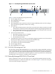
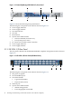
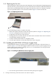
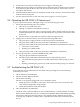
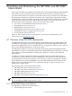
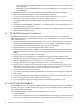

Figure 3-2 Externally Managed ISR 9024 S/D, Front Panel
2
1 3
4
5
6 7
8
9
Figure 2-3 shows the following front panel features:
The following list corresponds to the callouts shown in Figure 3-2.
1. Power supply indicator.
2. Power supply module.
3. Fan unit indicator.
4. Fan unit.
5. Reset button.
6. System status LEDs include:
• Info-User defined (for future use).
• Pwr-System power status.
7. I²C Connector. Provides serial I²C interface.
8. Power supply indicator.
9. Power supply module.
3.1.3 ISR 9024 S/D Rear Panel
The rear panel is identical in all ISR 9024 S/D RoHS compliant configurations and is shown in
Figure 3-3.
Figure 3-3 ISR 9024 S/D Rear Panel (InfiniBand Ports)
2
1
3
4
5
6
The following list corresponds to the callouts shown in Figure 3-3:
1. IEC power receptacle.
2. 24 4x InfiniBand ports.
3. Port LEDs include:
• Logical Link (Amber)
• Physical Link (Green)
4. Ethernet port.
5. System status LEDs include:
• Subnet manager LED
• Power Supply/Fan status LED
42 Installing and Maintaining the ISR 9024 S/D Interconnect (RoHS Compliant)