
HP Cluster Platform InfiniBand Interconnect Installation and User's Guide
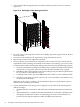
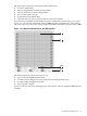


Figure 4-18 ISR 9096 InfiniBand Ports
1
3
2
4
6
5
The following features are shown in Figure 4-18:
1. Up to 4 sLB-24 InfiniBand line boards
2. Locking levers for inserting and removing the line boards
3. Blade installed in the sRBD
4. sRBD router blade drawer
5. A single sCTRL management module
6. Ethernet slots
4.6 Post-installation Tasks
Following the installation of the interconnect, your next tasks are as follows:
1. Cabling the interconnect, as described in Chapter 7. (This step requires that all appropriate
cluster nodes contain an HCA card, as described in Chapter 8.)
2. Powering up and visually inspecting the LED status lights to ensure that all devices and
modules are functioning.
3. Performing initial chassis configuration (setup) tasks, such as assigning IP addresses and
fabric device names, as described in the Voltaire InfiniBand Fabric Management and Diagnostic
Guide.
4. Verifying the cluster configuration, as described in Voltaire InfiniBand Fabric Management and
Diagnostic Guide.
Use the following procedure to verify that the ISR 9XXX starts up properly:
1. Check the status of the power supply LEDs on the front panel to ensure that the power
supplies are operating correctly.
2. Listen and check for airflow to make sure the fan assembly is operating correctly.
3. Check the status of the system LEDs to verify that the system is running and operational.
4. Verify that the following connections are operational by checking their status LEDs:
a. Gigabit Ethernet.
b. InfiniBand.
c. 10/100 Ethernet management.
See Chapter 9 and the Voltaire InfiniBand Fabric Management and Diagnostic Guide to isolate and
resolve the problem if any of the LEDs are not displaying the correct status.
4.6 Post-installation Tasks 67