HP Cluster Platform Myrinet System Interconnect Guide Part Number: A-CPMYI-1A May 2005 Revision/Update Information: Version 1.0 Product Version: HP Clusters This manual describes the Myricom Myrinet system interconnects used in HP Cluster Platform solutions.
© Copyright 2005 Hewlett-Packard Development Company, L.P. The information contained herein is subject to change without notice. The only warranties for HP products and services are set forth in the express warranty statements accompanying such products and services. Nothing herein should be construed as constituting an additional warranty. HP shall not be liable for technical or editorial errors or omissions contained herein. Printed in the United States.
Contents About This Manual 1 Myrinet interconnect overview 1.1 1.2 1.3 2 Switch card . . . . . . . . . . . . . . . . . . . . . . . . . . . . . . . . . . . . . . . . . . . . . . . . . . . . . . . . . . . . . . . . . . . . Spine card . . . . . . . . . . . . . . . . . . . . . . . . . . . . . . . . . . . . . . . . . . . . . . . . . . . . . . . . . . . . . . . . . . . . . . Monitoring line card . . . . . . . . . . . . . . . . . . . . . . . . . . . . . . . . . . . . . . . . . . . . . . . . . . . . . . . . . .
1-5 1-6 2-1 2-2 2-3 2-4 3-1 3-2 3-3 3-4 3-5 3-6 3-7 5-1 5-2 5-3 5-4 5-5 5-6 5-7 5-8 5-9 5-10 5-11 5-12 5-13 128-Port Myrinet System Interconnect . . . . . . . . . . . . . . . . . . . . . . . . . . . . . . . . . . . . Fully Populated 128-Port Myrinet System Interconnect . . . . . . . . . . . . . . . PCI Identification Label . . . . . . . . . . . . . . . . . . . . . . . . . . . . . . . . . . . . . . . . . . . . . . . . . . . . . Single-port XP PCI Rev. D card . . . . . . . . . . . . . . . . . . . . . . . . .
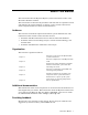
About This Manual This manual describes the Myricom Myrinet system interconnects used in some HP Cluster Platform solutions. This manual does not describe the procedures and tools that are required to install and configure the system hardware or software. It does contain references for cluster components that have their own documentation. Audience This manual is intended for experienced hardware system administrators.
Symbols in text zk-2071 ! zk-2071 ! WARNING: Text set off in this manner indicates that failure to follow directions in the warning could result in bodily harm or loss of life. CAUTION: Text set off in this manner indicates that failure to follow directions in the caution could result in damage to equipment or loss of information. _______________________ Important _______________________ Text set off in this manner presents clarifying information or specfic instructions.
1 Myrinet interconnect overview The high-speed Myrinet system interconnect is used in some HP Cluster Platform solutions. The chassis for the interconnect is 5U or 9U, depending on the cluster configuration. A PCI adapter card connects each application node in the cluster to the interconnect. The PCI card can have single (XP) or dual (2XP) ports. This chapter presents the following information about the Myrinet system interconnect: • A description of the interconnect characteristics (Section 1.
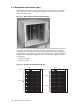
1.2 Backplane and chassis types The Myrinet interconnect used in an HP Cluster Platform can be a 5U (64-port) or 9U (128-port) chassis. The backplane (Figure 1-2) provides connectivity for the 8-port switch cards. Figure 1-2: Myrinet System Interconnect Backplane For configurations greater than 128 total nodes, you must build the network out to increase the number of available ports and to maintain the cross-sectional bandwidth.
The 128-port, node-level switch in a federated configuration provides 64 downlinks to nodes and dedicates the other 64 ports to uplinks that provide connectivity to deeper parts of the network. A top-level switch, another Myrinet system interconnect, consolidates the uplinks from two node-level switches. Each switch supports up to 128 links, 64 links from each node-level switch; therefore, two top-level switches are necessary to support configurations up to 256 nodes.
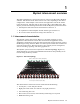
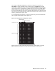
Figure 1-5: 128-Port Myrinet System Interconnect xc-013B-IG Table 1-1 explains the chassis types, and the types and location of line cards within the interconnects.
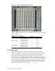
Figure 1-6: Fully Populated 128-Port Myrinet System Interconnect 4 Application nodes start here, move left, and then down to the next card. Switch cards are numbered 0-15, beginning with the card below the monitoring line card (1). If the control node is connected to the system interconnect, it populates the highest available port. The utility nodes follow the control node, move right, and then up to the next card.
2 PCI cards Every node in a cluster that uses a Myricom system interconnect has a PCI host bus adapter (HBA), and each host interface has a connection to the interconnect. This chapter presents the following information relating to the three versions of the PCI card that might be used in an HP Cluster Platform solution: • General characteristics of the PCI card (Section 2.1) • A description of the single-port XP PCI Rev. D card (Section 2.2) • A description of the dual-port 2XP PCI Rev.
2.2 Single-port XP PCI card The single-port XP PCI card (Figure 2-2) is the Myricom Rev. D card. It supports one X-port interface and one PCI-X interface. Figure 2-2: Single-port XP PCI Rev.
Table 2-1 shows the single-port XP PCI card’s technical specifications. Table 2-1: XP PCI Host Interface Card Specifications Feature Specifications XP PCI card 64-bit PCI-X Notes PCI low-profile PCI short card Bus speed 75-133 MHz PCI-X slots 66 MHz (3.3V) PCI slots Memory 2 MB Memory bandwidth 1,800 MB/s Processor 225 MHz RISC LANai XP Data rate 490 MB/s User-level bidirectional data rate.
Figure 2-3: Myricom 2XP PCI Rev.
Table 2-3 describes the technical specifications for the 2XP PCI card. Table 2-3: 2XP PCI Card Specifications Feature Specifications Notes 2XP PCI card 64-bit PCI-X and PCI protocols Can be used in any 3.3V PCI slot. Bus speed 66-133 MHz Capable of peak PCI date rates at the limits of the PCI-X or PCI buses (1067MB for 64-bit, 133MHz PCI-X and 533MB for 64-bit at 66 MHz). Local memory 2 MB Memory bandwidth 2664 MB/s Processor 333 MHz RISC LANai 2XP.
Figure 2-4: Myricom 2XP PCI Rev.
3 Switch, spine and monitoring line cards The Myrinet system interconnect uses three types of cards. This chapter presents the following information: • A description of the switch card (Section 3.1). • A description of the spine card (Section 3.2). • A description of the monitoring line card (Section 3.3). 3.1 Switch card The Myrinet system interconnect 8-port switch card (Figure 3-1) connects up to eight nodes together.
Item Description 3 Port identification number 4 Type LC fiber port Figure 3-3 identifies the external features of the Myrinet system interconnect 8-port GigE switch card. Each GigE port has two green LEDs in the RJ45 connector. The right LED indicates link activity, and the left LED indicates traffic. Figure 3-3: Myrinet system interconnect 8-Port GigE switch card 15 X Y 13 14 Z 11 12 [ 10 9 8 \ Item Description 1 Card latch in unlocked position. 2 Switch card power status light.
Figure 3-4: Block Diagram of the gigabit ethernet switch card Myrinet Backplane Interface 3210 7654 dual + 12V Serial link Power & hot-swap circuits Scan path Sense & Clocks Control XBar16 Lanai-XM-based Myrinet-GbE conversion for each of these 8 ports 15 14 13 12 11 10 9 8 GbE Front-panel Ports HPTC-0017 XBar16 The XBar16 is a 16-port crossbar switch implemented in a single chip.
Figure 3-5: Spine Card Block Diagram Backplane Interface 76 54 µC Clocks 32 10 dual +12V Power & hot-swap circuits Serial link Sense & Control Physical-Level Conversion Circuits 7 6 5 4 3 Front-Panel Ports 2 1 0 3.3 Monitoring line card All system interconnects must have a monitoring line card installed.
Figure 3-6: Monitoring Line Card The Ethernet ports are dual redundant and have the same MAC address. The Ethernet MAC address is shown on a label on the front panel of the line card. The dual-redundant, automatic-failover feature is implemented in the firmware. The Ethernet ports also require a DHCP server on the network to give the card’s microcontroller an IP address and subnet mask. The standard firmware supports two software interfaces over the Ethernet connections: HTTP Web server and SNMP.
4 LED indications and diagnostics If you encounter any operational problems with your Myrinet system interconnect, you can use the LEDs on each switch port and PCI interface to diagnose and correct the problem. The monitoring line card installed on the system interconnect also can be used for diagnostics. This chapter presents the following information: • An explanation of the line card and PCI LEDs (Section 4.1). • An explanation of how to use LEDs for diagnostic purposes (Section 4.2).
b. 3. Verify that the host booted correctly by making a connection to the host through its management console. If it did not boot correctly, check the startup procedures in the software documentation and see the HP ROM-Based Setup Utility User Guide, which is provided in the server’s documentation set. If the yellow LED on a server’s PCI card is not illuminated, the GM-2 MCP firmware is not loaded or is not running. Use the following procedure to check the PCI card: a.
• Enable or disable detection traps To configure network access to the monitoring line card, use the following procedure: 1. Obtain the MAC address from the label on the front panel of the monitoring line card. 2. Log in to the control node as root and edit the /etc/dhcpd.conf file to add a fixed IP address for the Myrinet line card MAC address. The following example shows a typical entry in the dhcpd.
5 Replacing components Several components can be replaced in the Myrinet system interconnect: This chapter presents the following instructions relating to the replaceable components: • Installing a monitoring line card (Section 5.1). • Removing and installing an 8-port line card (Section 5.2). • Replacing a fan tray (Section 5.3) • Replacing a chassis (Section 5.4) 5.1 Installing a monitoring line card To install a monitoring line card in your Myrinet system interconnect switch, do the following: 1.
5.1.1 Rebooting the monitoring line card The easiest way to reboot a Myrinet interconnect is with a Web browser. In the following steps, uc denotes microcontroller: 1. Get the main page (http://switchname). 2. Click on the link "Slot 56 (big uc)." 3. Select "reboot" from the menu "commandForBigUc." 4. Click on Apply. This does not reset all the counters in other line cards. To do this, you have to also reboot each line card microcontroller, as follows: 1. Get the main page (http://switchname). 2.
Figure 5-2: Ejecting a Switch Card It is normal that the ejection is a little stiff while the line card’s front panel is in contact with the front panel or bezels above and below. The bottom of each front panel and the bottom of the top bezel have spring gasketing as an EMI seal. Once the handles reach their outward extreme, the line card should slide easily out of the card cage (Figure 5-3). Figure 5-3: Sliding a Switch Card 3.
_________________________ Note _________________________ Do not operate a Myrinet interconnect for extended periods with missing line cards. Use blank panels to fill in any empty line card slots. The front of the enclosure needs to be closed both for the efficiency of the fan cooling and to avoid electromagnetic interference (EMI). 5.3 Replacing a fan tray The fan tray is hot swappable and monitored via the line monitor card.
Figure 5-6: Interconnect Fan Tray 5.4 Replacing an interconnect chassis The communications ports on the interconnect face toward the rear of the rack. The location of the interconnect in the rack depends on the specific configuration of your cluster. Up to four 14U interconnects might be installed in a single rack, and their rack positions might vary depending on the configuration rules for your system.
5. Disconnect and remove each fiber-optic cable until all ports are unplugged. Secure the cables out of the interconnect’s removal path. _______________________ Note _______________________ Observe the maximum bend radius for fiber-optic cables. Bending the cables too much can cause the glass core to break. A good rule of thumb is to never bend more than a 2-inch radius. 6. Use a #1 Phillips screwdriver to remove the four 6-32 x .
Figure 5-8: Sliding Interconnect Chassis from the Rack Rear of Rack 8. Move the interconnect to a suitable work surface. Retain all screws for reuse. Use only the 6-32 x .375 in Phillips pan-head screws to attach the retainer brackets to the chassis. Use of incorrect screws might damage components. Procedure for 9U Interconnect To remove a 9U system interconnect from the rack, use the following procedure: 1.
5. At the rear of the rack, disconnect the cables after first ensuring that the cables are properly labeled for their appropriate ports. This is important if you are planning to replace a defective interconnect. Remove the cables from the cable management straps, and route them carefully out of the way of the interconnect’s removal path. _______________________ Note _______________________ Observe the maximum bend radius for cables. Bending the cables too much can cause damage. radius. 6.
5.4.2 Swapping the line cards When replacing an interconnect chassis, the monitoring line card and all switch and spine cards must be removed from the current interconnect and moved into the new chassis. Before starting the removal process, you must prepare the new interconnect for the line cards. Place the new interconnect chassis on the same work surface as the chassis that is being replaced.
5.4.3 Replacing the interconnect in the rack After removing the interconnect and swapping the line cards, you are ready to replace the interconnect in the rack. You insert the interconnect chassis from the rear of the rack, with its front panel (the connection ports) facing the rear of the rack. There are two procedures for this operation, depending upon the size of the interconnect. Both procedures are explained in this section.
6 Powering up procedure To power up a Myrinet system interconnect, plug the power cord into the standard C14 power jack labeled 100–127/200–240 V-. The power cord is rated 10A for the 5U interconnect, and 15A for the 9U chassis. There is no power switch on the enclosure, which prevents an accidental network shutdown. Typical operating temperatures for the components of the switch are in the range of 30–39 degrees Celsius (86–102 Fahrenheit).
6-2 Characteristic 5U Chassis Operating 15% to 80% @ 104° F Nonoperating 90% @ 149° F Powering up procedure 9U Chassis
Index Numbers and Special Characters H 2XP PCI Rev. E, 2-3 Rev.
spine card, 3-3 monitoring line card, 3-4, 4-2 installing, 5-1 network access, 4-2 rebooting, 5-2 reseating, 4-3 MPI, 1-1 N network access, 4-2 node-level switch, 1-2 nonfederated configuration, 1-3 P password default, 4-3 PCI card, 1-1, 2-1 identification label, 2-1 LEDs, 2-1 Rev. D, 2-2 Rev. E, 2-3 Rev.