
Myrinet System Interconnect Guide

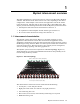
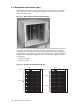
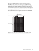
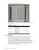

Figure 1-5: 128-Port Myrinet System Interconnect
xc-013B-IG
Table 1-1 explains the chassis types, and the types and location of line cards within
the interconnects.
Table 1-1: Chassis types
Chassis Type
Component
Quantity
Location
Bounded chass is M3-E128 17 slot chassis 1
Monitoring Line Card
1SlotM
8 Port Switch Line Card 1 -- 16 Slot 0 - 15
Node level chassis M3-E128 17 slot chassis 1
Monitoring Line Card
1SlotM
8 Port Spine Card
1--8 Slot0-7
8 Port Switch Line Card 1 -- 8 Slot 8 - 15
Top level chassis
M3-E128 17 slot chassis 1
Monitoring Line Card
1SlotM
8 Port Spine Card
1--16 Slot0-15
1.3 Wiring rules
When you connect cables to a Myrinet system interconnect in a bounded
configuration with 128 or fewer nodes, you connect downlinks to the application
nodes and utility nodes starting from opposite sides of the switch (Figure 1-6).
When populating node-lev el Myrinet system interconnects in a m odular
configuration, you connect downlinks to the application nodes and utility nodes
from one side of the s witch and uplinks to the top-level switches from the opposite
side of the switch. You maintain a ratio of one -to-one between the 8-port spine
cards and the 8-port switch cards in each node-level chassis. Node level chassis
slots 0-7 are reserved for spine cards (uplinks). Node level chassis slots 8-15 are
reserved for switch cards (node connections).
1-4 Myrinet interconnect overview