
Myrinet System Interconnect Guide
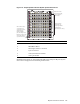

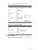
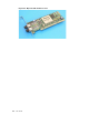
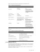
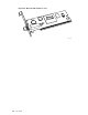
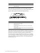

Figure 1-6: Fully Populated 128-Port M yrinet System Interconnect
4
Application nodes
start here, move left,
and then down to
the next card.
If the control node is
connected to the
system interconnect,
it populates the
highest available
port. The utility nodes
follow the control node,
move right, and then
up to the next card.
Switch cards are
numbered 0-15,
beginning with the
card below the
monitoring line card (1).
Item Description
1
M3-M monitoring line card
2
M3-M MAC address
3
Status light (common to all cards)
4
8-port switch card
5
Card ejection/insertion handles
6
Cooling fan module
Detaile
d wiring tables are presented in the HP Cluster Platform Myrinet System
Interco
nnect Configuration and Cabling Tables Guide .
Myrinet interconnect overview 1-5