
Myrinet System Interconnect Guide


3
Switch, spine and monitoring line cards
The Myrinet system interconnect uses three types of cards. This chapter presents
the followin g information:
• A description o f the switch card (Section 3.1).
• A description of the spine card (Section 3.2).
• A description of the monitoring line card (Section 3.3).
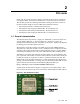
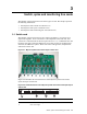
3.1 Switch card
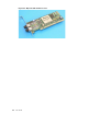
The Myrinet system interconnect 8-port sw itch card (Figure 3-1) connects up to
eight nodes together. It has connectors to the backplane on the back side, and
connectors to external links on the front panel. It has a Status LED located on the
left front side of the card. This LED turns green after passing its self diagnostics.
If it fails, the LED turns yellow. The se t ests assess voltage levels, temperatures,
and internal status bits.
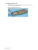
Figure 3-1: Myrinet system Interconnect 8-port switch car
d
xc-014-ig
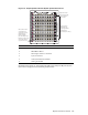
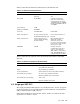
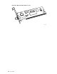
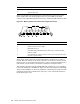
Figure 3-2 identifies the external features of the M yrine t system interconnect
8-port fiberoptic switch card.
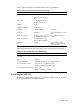
Figure 3-2: External features of the Myrinet system interconnect fiberoptic 8-port
switch card
Item Description
1
Switch card status light
2
Port status light
Switch, spine and monitoring line cards 3-1