
Myrinet System Interconnect Guide


Item Description
3
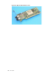
Port identification number
4
Type LC fiber port
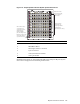
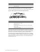
Figure 3-3 identifies the external features of the M yrine t system interconnect
8-port GigE switch card. Each GigE port has two green LEDs in the RJ45
connector. The right LED indicates link activity, and the left LED indicates traffic.
Figure 3-3: Myrinet system interconnect 8-Port GigE switch card
8
9
10
11
12
13
14
15
YXZ[\
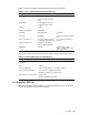
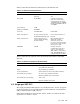
Item Description
1
Card latch in unlocked position.
2
Switch card power status light.
3
RJ45 Ethernet port.
4
Port LEDs. The right LED indicates link activiy, and the left LED
indicates traffic.
5
Port identification number, which is used as part of the port ID string
for point-to-point cabling.
Every 8-port switch card in the system interconnect is numbered 8–15. This is
normal. The port number on the panel of the line card is only one element used to
identify a port. In port numbering discussions, a port is uniquely identified by the
rack number, chassis number, slot number, and the line card port number.
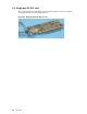
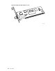
The backplane interface includes 8 SAN-2000 links num bered 0-7, corresponding
to the port numbering of the XBar16. Figure 3-4 show s the backplane of the GigE
switch card, and Figure 3-5 shows the backplane of the fiberoptic switch card. The
backplane interface also includes dual +12V power, and a serial-link interface to
the monitoring line card.
3-2 Switch, spine and monitoring line cards