
Myrinet System Interconnect Guide
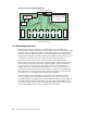
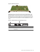

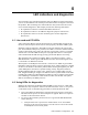
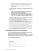

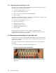

Figure 3-5: S pi n e Card Block Diagram
µC
Clocks
Backplane Interface
01234567
Front-Panel Ports
Serial link
Sense &
Control
Power & hot-swap
circuits
Physical-Level Conversion Circuits
dual +12V
0
1
2
3
4
5
6
7
3.3 Monitoring line card
All system interconnects must have a monitoring line card installed. The
monitoring line card is powered from the dual +12V sources in the same way a s the
port line cards, and likewise includes a small microcontroller to monitor internal
functions, voltages, and temperatures. The m onitoring line card is keyed by the
position of the backplane connector so that it can be inserted only in the top slot of
an enclosure, and so that port line cards cannot be inserted into this slot.
The main circuitry on the card is a microcontroller with RAM and flash
memory that com municates internally via 26 individual serial links with small
microcontrollers on the port line cards, backplane XBars, the fan-monitoring
board, an d on t h e m o nitoring line card itself. Self-test, board identification,
voltage monitoring, and temperature monitoring are some of the functions of
the monitoring line card. All status information is reported on demand through
the serial link to the main microcontroll er. The microcontroller will shut off the
line-card power on over-temperature or o ther fault conditions.
The front panel of the m onitoring line card (Figure 3-6 and Figure 3-7) has
a Status LED, green for operating and yello w for fault. The card also has
dual-redundant 10-Base Ethernet ports. Each Ethernet port has a green LED. If
the LED is off, the card is not connected to an active port. If the LED is on, the
card is connected to an active port. If the L ED is blinking , th ere is traffic. There
are two other LEDs for the +12V A and B internal power buses.
3-4 Switch, spine and monitoring line cards