
Myrinet System Interconnect Guide

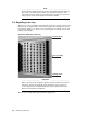

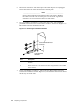

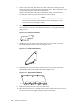


Figure 5-6: Interconnect Fan Tray
5.4 Replacing an interconnect chassis
The communications ports on the interconnect face toward the rear of the rack.
The location of the interconnect in the rack depends on the specific configuration
of your cluster. Up to four 14U interconnects might be installed in a single rack,
and their rack positions m ight vary depending on the configuration rules for your
system. The most common location for the 3U and 5U interconnects is at rack
position 0, at the very bottom of the rack.
_______________________ Warning _______________________
A fully loaded 14U interconnect weighs approximately 32 kg (70 lb).
Removing a fully lo aded 14U chassis requires at least two people
suitably equipped and trained to lift the interconnect out of the rack.
If you are removing any size switch f rom the topmost position in a
rack, always use two people and a stable, elevated work platform or
equivalent.
5.4.1 Removing the interconnect from the rack
You remove an interconnect from the rear of the rack, which might have limited
working room depending on how close the rack is located to walls or other racks.
Take note of the safety warning concerning the s afe handling of the interconnect.
A Myrinet system interconnect with a a 5U (9-slot) chassis uses a different type of
rack kit than the larger Myrinet interconnect models. The larger interconnect also
requires a ventilating baffle. Subsequently,therearetwodifferentproceduresfor
removing and replacing an interconnect chassis in the rack. The two procedures
are described in this section.
Procedure a 5U Interconnect
To remove a 5U sys tem interconnect from the rack, use the following procedure:
1. Bring the cluster to an appropriate state for switch component rem oval and
put the rack into a safe and stable state for component removal.
2. At the rack’s power distribution unit (PDU), power off the circuit that supplies
power to the interconnect. Disconnect the power cable at the rear of the
interconnect chassis.
3. Prepare a suitable work surface and clear a pathway for removal of the
interconnect. Ensure that there are no cables or other obstructions underfoot.
4. At the rear of the rack, ensure that the high-speed network cables are properly
labeled for their appropriate ports. This is important if you are planning to
replace a defective interconnect.
Replacing components 5-5