
Myrinet System Interconnect Guide

1-5
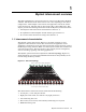
128-Port Myrinet System Interconnect .................................... 1-4
1-6
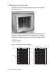
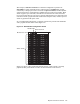
Fully Populated 128-
Port Myrinet System Interconnect ...............
1-5
2-1
PCI Identification Label ..................................................... 2-1
2-2
Single-port XP PCI Rev. D card ............................................ 2-2
2-3
Myricom 2XP PCI Rev. E
card ..............................................
2-4
2-4
Myricom 2XP PCI Rev. F card .............................................. 2-6
3-1
Myrinet system Interconnect 8-port switch card ......................... 3-1
3-2
External features of
the Myrinet system interconnect fiberoptic
8-port switch card ............................................................. 3-1
3-3
Myrinet system interconnect 8-Port GigE switch card .................. 3-2
3-4
Block Diagram of the gigabit ethernet switch card ...................... 3-3
3-5
Spine Card Block Dia
gram ..................................................
3-4
3-6
Monitoring Line Card ........................................................ 3-5
3-7
External Features of the Monitoring Line Card ......................... 3-5
5-1
Unlocking Switch Ca
rd Handles ...........................................
5-2
5-2
Ejecting a Switch Card ....................................................... 5-3
5-3
Sliding a Switch Card ........................................................ 5-3
5-4
Backplane Pow er Con
nector ................................................
5-3
5-5
Removing a Fan Tray ........................................................ 5-4
5-6
Interconnect Fan Tray ....................................................... 5-5
5-7
Removing the Retainer Brackets ........................................... 5-6
5-8
Sliding Interconnect Chassis from the Rack .............................. 5-7
5-9
Blanking Plate ................................................................ 5-7
5-10
Hold-Down Bracket ........................................................... 5-8
5-11
Left Bracket Retainer ........................................................ 5-8
5-12
Right Bracket Reta
iner ......................................................
5-8
5-13
Removing the Existing Brackets ........................................... 5-9
Tables
1-1
Chassis types .................................................................. 1-4
2-1
XP PCI Host Interface Card Specifications ............................... 2-3
2-2
XP PCI Card Physical Characteristics .................................... 2-3
2-3
2XP PCI Card Speci
fications ................................................
2-5
2-4
2XP PCI Card Physical Characteristics ................................... 2-5
i
v Contents