
Myrinet System Interconnect Guide


1
Myrinet interconnect overview
The high-speed Myrinet system interconnect is u sed in some HP Cluster Platform
solutions. The chassis for the interconnect is 5U or 9U, depending on the cluster
configuration. A PCI adapter card connects each application node in the cluster
to the interconnect. The PCI card can havesingle(XP)ordual(2XP)ports. This
chapter presents the following information about the Myrinet system interconnect:
• A description of the interconnect characteristics (Section 1.1)
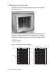
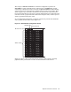
• An explanation of the backplane and the chassis types (Section 1.2)
• An overview of the interconnect wiring rules (Section 1.3)
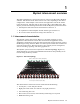
1.1 Interconnect characteristics
The Myrinet system interconnect (Figure 1-5) provides transport for user
application communication between the control node and application nodes.
Applications communicate across the interconnect w ith message protocols, such as
the M ess age Passing Interface (MPI). U ser I/O requests for files also com m unicate
across the interconnect. The interconnect is a ls o used for proces s management,
such as launching, signaling, and exiting applications.
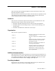
The Myrinet syste m interconnect implements a fat tree topology (Figure 1-1),
which m ax imizes cross-sectional bandwidth an d minimizes the possibility of on e
transfer being blocked by another.
Figure 1-1: Fat Tree Topology
8
hosts
8
hosts
8
hosts
8
hosts
8
hosts
8
hosts
8
hosts
8
hosts
8
hosts
8
hosts
8
hosts
8
hosts
8
hosts
8
hosts
8
hosts
8
hosts
Ports to up to 128 hosts (line cards)
Spine of the fat tree network (backplane)
The characteristics of the i nterconnect switch include the following:
• 5U (64-port) , or 9U (128-port) chassis
• Eight-port switch cards (one card for every eight processors)
• One monitoring line card
• Flow control, error control, and continuity monitoring on every link
• HTTP monitoring card
Myrinet interconnect overview 1-1